Through-curve anti-deflection mechanism for sanding device at end part of locomotive car body

A sand spreading device and anti-deflection technology, which is applied in locomotives and other directions, can solve the problems of insufficient traction, inability to effectively improve the adhesion coefficient between wheel and rail, idling, etc., and achieve the effect of improving the adhesion coefficient

Active Publication Date: 2014-06-18
SOUTHWEST JIAOTONG UNIV
View PDF6 Cites 6 Cited by
  • Summary
  • Abstract
  • Description
  • Claims
  • Application Information

AI Technical Summary

Problems solved by technology

However, at present, the sand spreading devices at the end of the locomotive car body (the front end of the first bogie and the rear end of the second bogie) are all designed according to the straight track. The nozzle of the sanding hose at the end of the car body and its sanding device will deviate to the outside of the outer track, resulting in a large amount of sand being sprinkled on the outside of the outer track or the inner side of the inner track (based on the centerline of the inner and outer tracks) , the sand cannot be well sprinkled on the rail surface, and the adhesion coefficient between the wheel and rail cannot be effectively improved
When the locomotive equipped with the sand spreading device at the end of the locomotive car body passes the curved track, especially the small radius curved track, the wheels will still slip, idling, the traction is insufficient, and the wheel and rail wear will be large

Method used


Image

  • Through-curve anti-deflection mechanism for sanding device at end part of locomotive car body
  • Through-curve anti-deflection mechanism for sanding device at end part of locomotive car body
  • Through-curve anti-deflection mechanism for sanding device at end part of locomotive car body

Examples


Embodiment

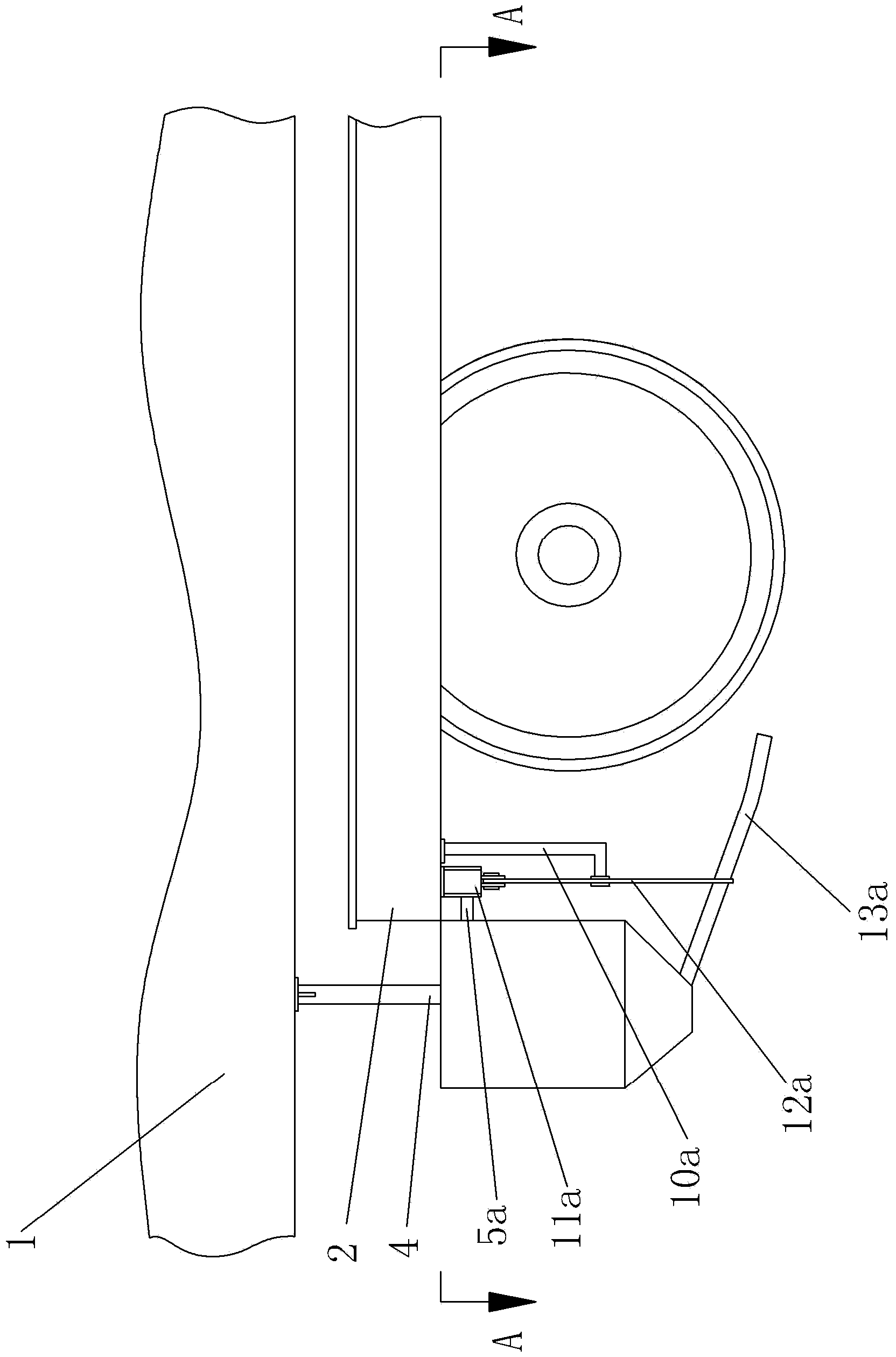
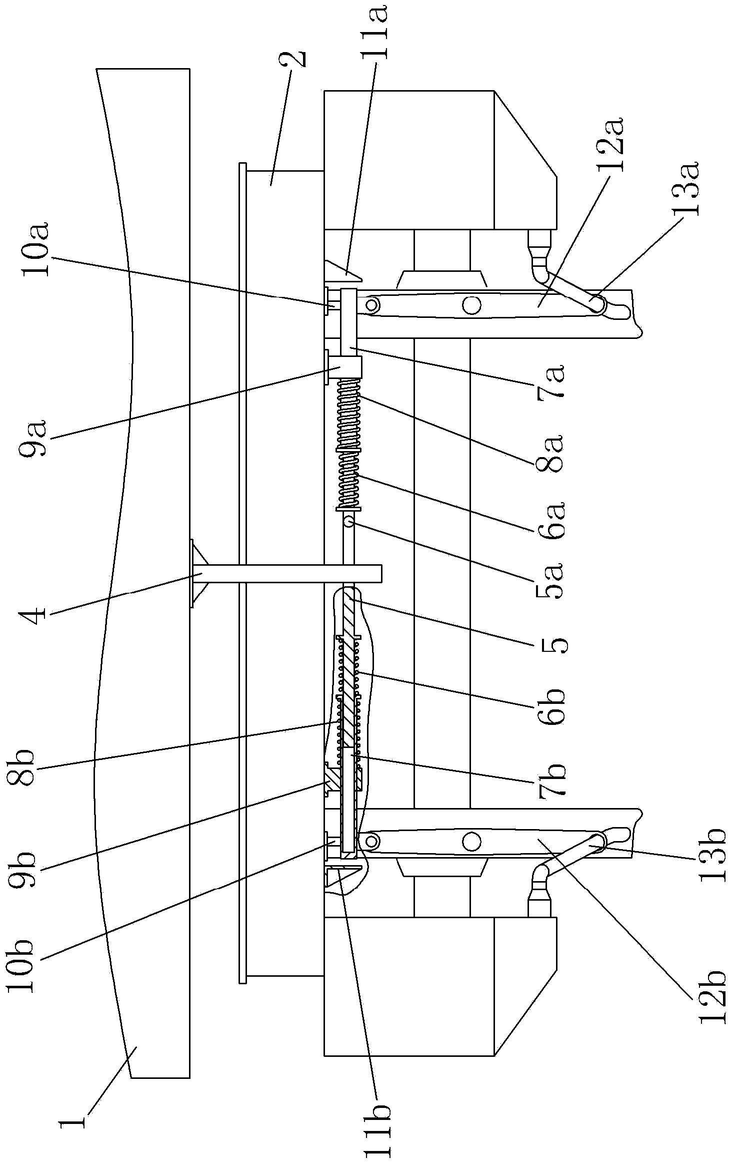
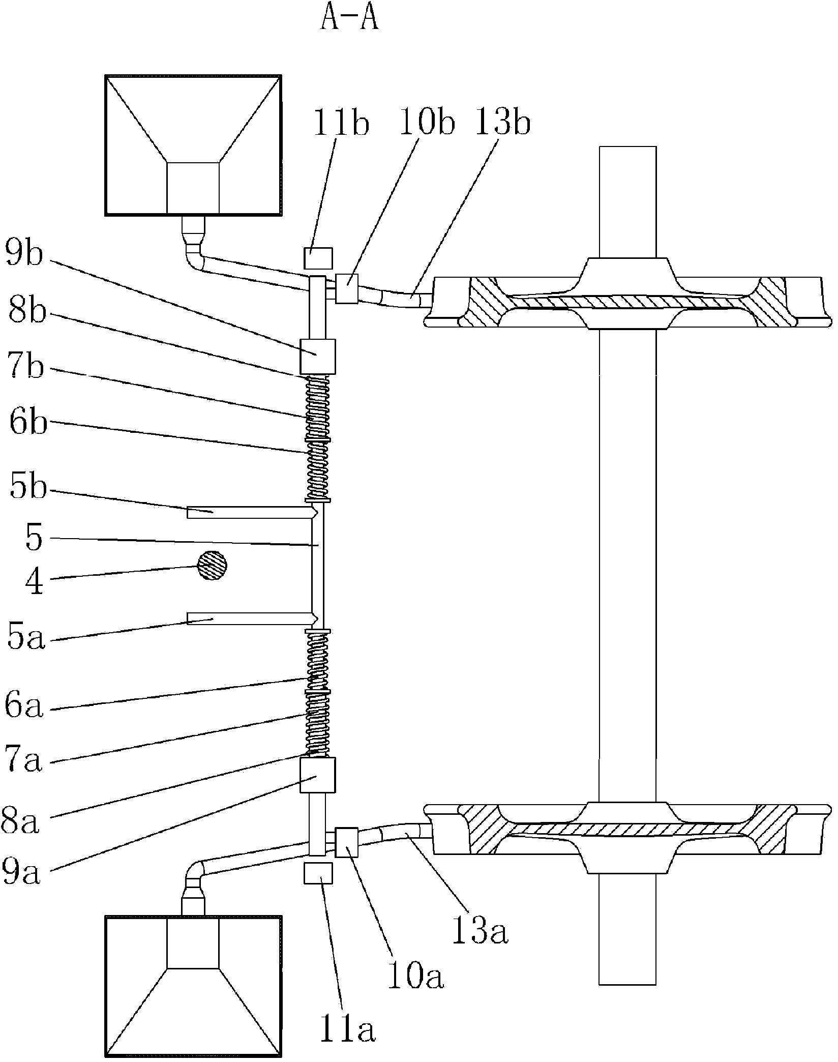
[0027] Figure 1~3 It is shown that a specific implementation of the present invention is a curved anti-deflection mechanism of a sand spreading device at the end of a locomotive body, wherein:

[0028] The middle part of the right sanding hose 13a of the sanding device at the end of the locomotive body 1 is matched with the hose connection hole at the lower end of the right reversing lever 12a. The middle part of the right reversing lever 12a is hinged on the right positioning rod 10a, and the right positioning rod 10a The upper end is rigidly connected to the end beam 2 of the locomotive frame; the upper end of the right reversing lever 12a is hinged to the right end of the lateral right sleeve 7a, and the middle of the right sleeve 7a is sheathed in the right sleeve seat 9a at the lower part of the end beam 2. In the cavity, the right sleeve return spring 8a is sleeved between the left end of the right sleeve 7a and the right sleeve seat 9a; the inner cavity of the right sleev...


PUM


Abstract

The invention discloses a through-curve anti-deflection mechanism for a sanding device at the end part of a locomotive car body. The middle of a left (right) sanding hose of the sanding device at the end part of the car body is matched with a connection hole at the lower end of a left (right) reversing lever; the middle of the left (right) reversing lever is hinged on a left (right) locating rod; the upper end of the left (right) locating rod is fixed on an end girder of a locomotive framework; the upper end of the left (right) reversing lever is hinged with the left (right) end part of a transverse left (right) sleeve; the middle of the left (right) sleeve sleeves into an inner cavity of the left (right) sleeve base at the lower part of the end girder; a left (right) sleeve reset spring sleeves the part between the right end of the left (right) sleeve and the left (right) sleeve base; the inner cavity of the left (right) sleeve is sleeved with the left (right) end of a cross bar; a left (right) front baffle rod is arranged in the middle of the cross bar near the left (right) part; the part between the left (right) front baffle rod of the cross bar and the left (right) sleeve is sleeved with a left (right) baffle rod reset spring; the lower end of an upright tube connected with the car body is arranged inside the space between the cross bar and the left (right) front baffle rod.

Description

Technical field [0001] The invention relates to a curve-crossing anti-deflection mechanism of a railway locomotive sand spreading device, in particular to a curve-crossing anti-deflection mechanism of a sand spreading device at the end of a locomotive body. Background technique [0002] In the case of heavy rain and humid air, the adhesion coefficient between the locomotive wheels and the track is reduced. When the locomotive passes the track, the wheels are prone to slipping and idling; on the one hand, insufficient traction or insufficient braking force is caused, on the other hand, the wheel and rail are rolling The friction becomes sliding friction, which increases the wear of the wheel and rail and reduces the life of the wheel and rail, especially when the radius of the curve is too small, the wear of the wheel flange is more serious. [0003] Four pairs of sand-spreading devices are installed on the locomotive body, the first pair of sand-spreading devices on the front end o...

Claims


Application Information

Patent Timeline
Patent Type & Authority Applications(China)
IPC IPC(8): B61C15/10
Inventor 李凡松邬平波聂依照曾京罗仁石怀龙唐阳
Owner SOUTHWEST JIAOTONG UNIV
Why Eureka
Try Eureka