
V-type pier steel-structure bridge folding and ejecting system

A rigid-frame bridge and bridge pier technology, which is applied in the field of V-shaped pier rigid-frame bridge closing and pushing system, can solve the problems of high pier stiffness, failure to achieve the effect of a bridge, restricting the development of the span of a continuous rigid-frame bridge, etc. Simple, improve long-term mechanical performance, prevent falling beams and lateral buckling

Pending Publication Date: 2018-04-20
LANZHOU UNIVERSITY OF TECHNOLOGY
View PDF0 Cites 0 Cited by
  • Summary
  • Abstract
  • Description
  • Claims
  • Application Information

AI Technical Summary

Problems solved by technology

However, the continuous rigid frame bridge is a multiple statically indeterminate structure. Generally, the piers of rigid frame bridges are fixed on the caps. The piers of V-shaped rigid frame bridges are very rigid. Relatively large secondary internal forces will have a very adverse effect on the structural system, often failing to achieve the ideal bridge-forming effect, and greatly limiting the development of the span of continuous rigid frame bridges. In order to reduce the impact of secondary internal forces on the structural stress Impact, to offset the horizontal deviation of the pier top caused by the temperature difference of closing and the shrinkage and creep of concrete, it needs to be pushed when closing, how to push? How to design a jacking system? What issues should be paid attention to during the promotion process? At present, there is no convenient and fast closing and pushing system for V-shaped rigid frame bridge

Method used


Image

  • V-type pier steel-structure bridge folding and ejecting system
  • V-type pier steel-structure bridge folding and ejecting system
  • V-type pier steel-structure bridge folding and ejecting system

Examples


Embodiment Construction

[0034] A V-shaped pier rigid frame bridge closing and pushing system of the present invention will be further described in detail below in conjunction with the accompanying drawings.

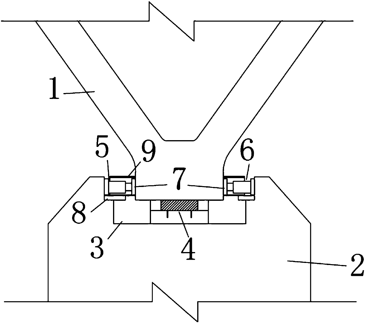
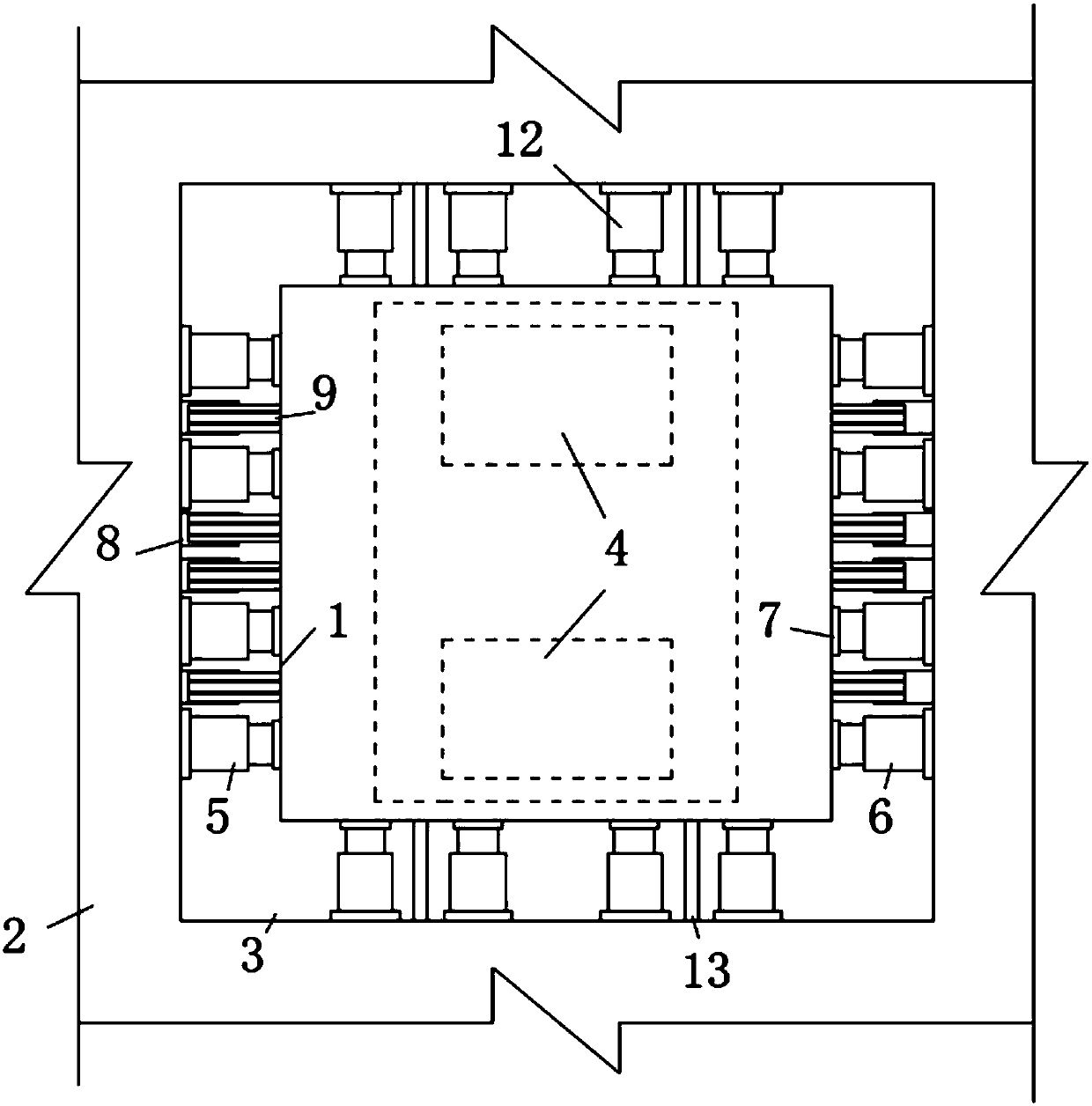
[0035] like Figure 1 to Figure 5 As shown, a V-shaped pier rigid frame bridge closing and pushing system of the present invention includes a pier 1 and a cap 2, a groove 3 is provided on the top of the cap 2, and two spherical steel supports are provided at the bottom of the groove 3. The bottom of pier 1 is supported on spherical steel bearings; a plurality of limit jacks 5 and push jacks 6 are arranged longitudinally between pier 1 and cap 2, and push jacks 6 and limit jacks 5 are located on opposite sides of pier 1. side; between the bridge pier 1 and the cap 2, a plurality of transverse jacks 12 are respectively arranged on both sides, and a plurality of I-beams 9 are embedded in the bottom of the pier 1, and the I-beams 9 are located between two limit jacks 5 or between two Between the tw...


PUM


Abstract

The invention provides a V-type pier steel-structure bridge folding and ejecting system which comprises a pier and a bearing platform. A groove is formed in the top of the bearing platform. A ball-type steel stand is arranged at the bottom of the groove. The bottom of the pier is supported on the ball-type steel stand. A plurality of limiting jacks and ejecting jacks are longitudinally arranged between the pier and the bearing platform and located on the two opposite sides of the pier. The two transverse sides between the pier and the bearing platform are each provided with a plurality of transverse jacks. A plurality of I-beams are embedded in the bottom of the pier and located between every two limiting jacks or ejecting jacks. Steel plates matched with the I-beams are arranged on the side wall of the groove. After ejecting ends, the steel plates and the I-beams are welded. The limiting jacks, the ejecting jacks and the transverse jacks eject the pier through cushion blocks. Steel pipes are arranged between every two transverse jacks. A stand limiting steel strip is arranged at the bottom of the groove. After ejecting ends, concrete is poured in the groove.

Description

technical field [0001] The invention relates to the technical field of bridge construction, in particular to a closing and pushing system for a V-shaped bridge pier rigid frame bridge. Background technique [0002] In recent years, since people have paid more and more attention to the beautiful design of bridges in addition to the safety, practicality and economic requirements of bridges, therefore, on the basis of conventional continuous girder bridges or continuous rigid frame bridges, designers People are more fond of rigid frame bridges with V-shaped piers. Compared with conventional rigid-frame bridges, this bridge has its own advantages: (1) From the analysis of the appearance of the bridge structure, the lower structure is V-shaped piers, and the upper structure is variable cross-section The concrete box girder structure or steel-concrete composite structure has a beautiful overall structure. The combination of the straight line of the V-shaped pier and the curve of t...

Claims


Application Information

Patent Timeline
Patent Type & Authority Applications(China)
IPC IPC(8): E01D21/00
CPCE01D21/00
Inventor 杨国俊杜永峰唐光武李喜梅李万润朱前坤张惠宁
Owner LANZHOU UNIVERSITY OF TECHNOLOGY
Learn More