
Testing system for hydraulic ram

A technology for testing systems and hydraulic cylinders, which is applied in fluid pressure actuation system testing, fluid pressure actuating devices, mechanical equipment, etc., and can solve problems such as inconvenience and low efficiency of hydraulic cylinder testing

Inactive Publication Date: 2014-06-18
SHANGHAI ELECTRICAL HYDRAULICS & PNEUMATICS
View PDF8 Cites 2 Cited by
  • Summary
  • Abstract
  • Description
  • Claims
  • Application Information

AI Technical Summary

Problems solved by technology

But at present, testing the hydraulic cylinder needs to be installed on the actual equipment to complete the test, which is very inconvenient, and the testing efficiency of the hydraulic cylinder is relatively low

Method used


Image

  • Testing system for hydraulic ram

Examples


Embodiment Construction

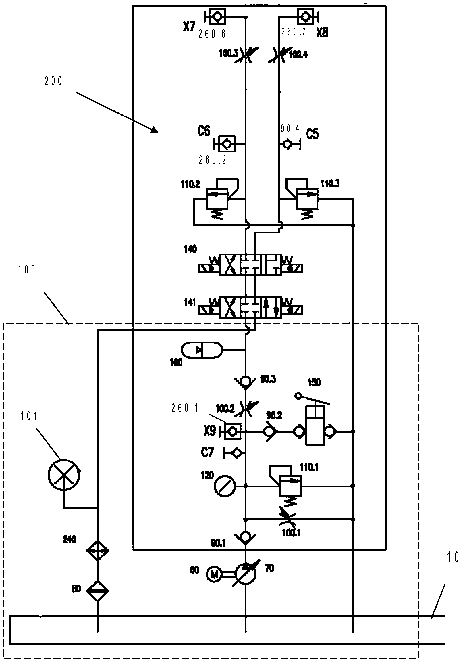
[0018] like figure 1 As shown, the hydraulic cylinder testing system of the present invention includes a hydraulic power source 100 and a main testing unit 200 .

[0019] Wherein, the main test unit 200 includes a first, three-position, four-way electromagnetic reversing valve 141, a second three-position, four-way electromagnetic reversing valve 140, a second relief valve 110.2, a third relief valve 110.3, a third throttle valve 100.3, and a fourth throttle valve 100.4.

[0020] The c oil port of the first three-position four-way electromagnetic reversing valve 141 is connected to the a oil port of the second three-position four-way electromagnetic reversing valve 140, and the c oil port of the second three-position four-way electromagnetic reversing valve 140 is connected to the second The inlet of the overflow valve 110.2, the second hydraulic control check valve 260.2 and the third throttle valve 100.3, the second hydraulic control check valve 260.2 is connected to the C6...


PUM


Abstract

The invention discloses a testing system for a hydraulic ram. The testing system for the hydraulic ram comprises a hydraulic power supply and a main testing unit, wherein the main testing unit comprises a first three-position four-way electromagnetic directional valve, a second three-position four-way electromagnetic directional valve, a second overflow valve, a third overflow valve, a third throttle valve and a fourth throttle valve; the hydraulic power supply is connected to the port a of the first three-position four-way electromagnetic directional valve; the port c of the first three-position four-way electromagnetic directional valve is communicated to the port a of the second three-position four-way electromagnetic directional valve; the port c of the second three-position four-way electromagnetic directional valve is communicated with the inlet of the second overflow valve and the third throttle valve. The testing system disclosed by the invention can be specially used for testing the hydraulic ram, and has the advantages that testing is convenient, and the testing efficiency is high.

Description

technical field [0001] The invention relates to a hydraulic test bench, in particular to a hydraulic cylinder testing system capable of testing hydraulic cylinders. Background technique [0002] At present, hydraulic technology is widely used in various fields. The produced hydraulic components and equipment need to be tested, such as hydraulic cylinders, hydraulic motors, and some hydraulically driven wind power. However, at present, the test of the hydraulic cylinder needs to be installed on the actual equipment to complete the test, which is very inconvenient, and the testing efficiency of the hydraulic cylinder is relatively low. [0003] Therefore, it is necessary to develop a hydraulic cylinder testing system that is convenient for testing and has high testing efficiency. Contents of the invention [0004] The technical problem to be solved by the present invention is to provide a hydraulic cylinder testing system to overcome the shortcomings of the prior art. [...

Claims


Application Information

Patent Timeline
IPC IPC(8): F15B19/00
Inventor 张杰
Owner SHANGHAI ELECTRICAL HYDRAULICS & PNEUMATICS
Learn More