
Reservoir for transmission fluid

A technology of accumulator and automatic transmission, which is applied in the field of accumulator, can solve the problems such as the reduction of space efficiency in the engine room, and achieve the effect of improving fuel efficiency and increasing the amount of time

Active Publication Date: 2014-06-18
HYUNDAI MOTOR CO LTD
View PDF5 Cites 1 Cited by
  • Summary
  • Abstract
  • Description
  • Claims
  • Application Information

AI Technical Summary

Problems solved by technology

[0010] In addition, since the oil cooler and heater for cooling the ATF are connected separately, the space efficiency of the engine room is reduced

Method used


Image

  • Reservoir for transmission fluid
  • Reservoir for transmission fluid
  • Reservoir for transmission fluid

Examples


Embodiment Construction

[0025] It should be understood that the term "vehicle" or "vehicular" or other similar terms as used herein generally includes motor vehicles such as passenger automobiles including sport utility vehicles (SUVs), buses, trucks, various commercial vehicles, including Boats and ships of all kinds, aircraft, etc., and includes hybrid vehicles, electric vehicles, combustion engine vehicles, plug-in hybrid electric vehicles, hydrogen powered vehicles, and other alternative fuel vehicles (e.g. fuel).

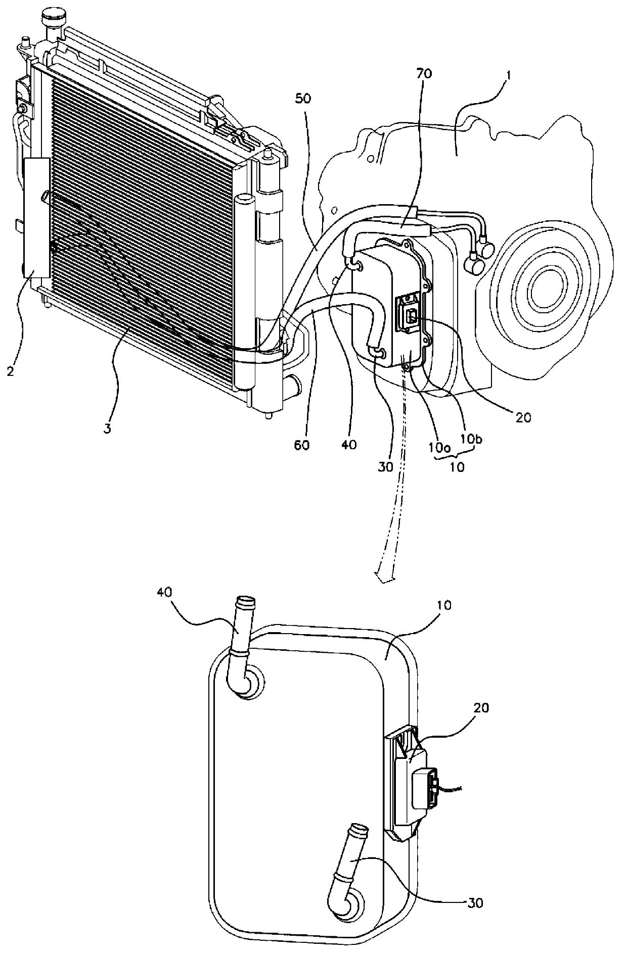
[0026] Hereinafter, a reservoir of transmission fluid such as automatic transmission fluid (ATF) according to an exemplary embodiment of the present invention will be described in detail with reference to the accompanying drawings.

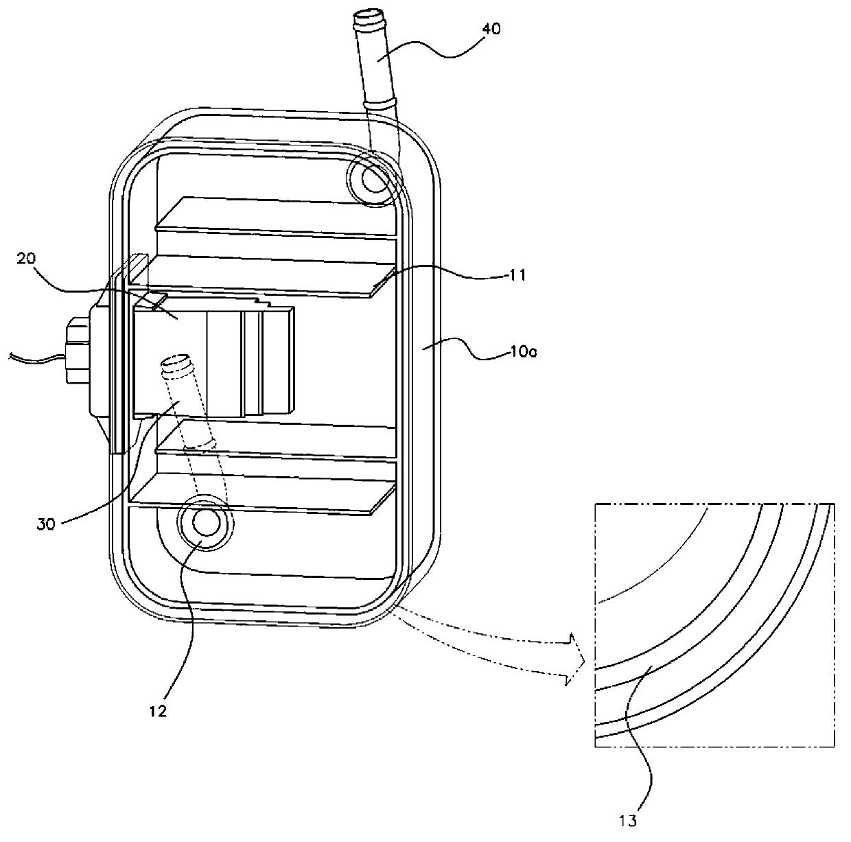
[0027] Such as figure 1 As shown, the reservoir of the ATF of the present invention is installed on one side of the transmission 1 and connected to the oil cooler 2 installed on the radiator 3 through hoses 50 , 60 and 70 . That is, an inlet joint 30 th...


PUM


Abstract

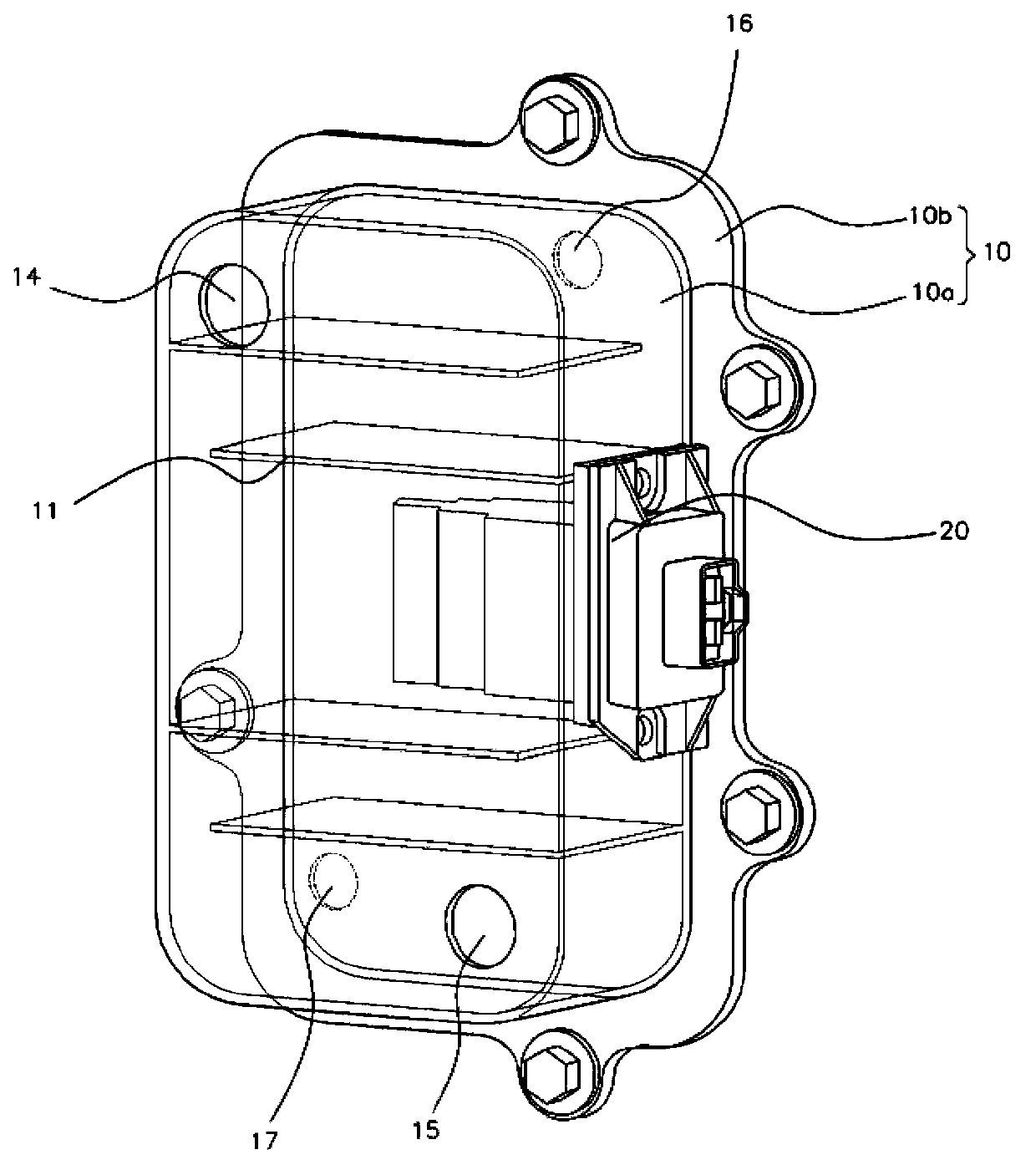
The invention discloses a reservoir for transmission fluid. In one embodiment, an Automatic Transmission Fluid (ATF) reservoir is provided. The reservoir includes housing that is combined with a transmission containing ATF and into / out of which the AFT flows. The reservoir also includes a heating body that is combined with the housing and heats the ATF flowing within the housing by generating heat when power is applied.

Description

[0001] Cross References to Related Applications [0002] This application claims priority under 35 U.S.C. §119 to Korean Patent Application No. 10-2012-0142145 filed in the Korean Intellectual Property Office on December 7, 2012, the entire contents of which are incorporated herein by reference. technical field [0003] The invention relates to a reservoir for transmission fluid such as ATF (Automatic Transmission Fluid). More particularly to a reservoir for an ATF capable of rapidly heating the ATF when power is applied using a PTC (Positive Temperature Coefficient) thermistor, and maintaining the temperature of the ATF to enable use during cold starts. Background technique [0004] As is known to those skilled in the art, automatic transmissions require the use of ATF to function properly. As such, the characteristics of the ATF have a significant impact on the efficiency, durability and operability of the transmission. [0005] ATF is used as a medium to transfer torque...

Claims


Application Information

Patent Timeline
Patent Type & Authority Applications(China)
IPC IPC(8): F16H41/24
CPCF16H57/0417F16H57/0412F16H57/0413F16H41/24F16H57/04B60K20/00
Inventor 吴东锡
Owner HYUNDAI MOTOR CO LTD
Learn More