Charging method and electronic device

A technology of electronic equipment and charging current, applied in the field of electronics, can solve the problem of slow charging rate and achieve the effect of improving the charging rate

Active Publication Date: 2014-06-18
LENOVO (BEIJING) CO LTD
View PDF11 Cites 10 Cited by
  • Summary
  • Abstract
  • Description
  • Claims
  • Application Information

AI Technical Summary

Problems solved by technology

[0006] Embodiments of the present invention provide a charging method and electronic equipment,

Method used


Image

  • Charging method and electronic device
  • Charging method and electronic device
  • Charging method and electronic device

Examples


Embodiment 1

[0087] The first embodiment of the present application provides a charging method, which is applied to an electronic device including a power storage unit, such as a notebook computer, a tablet computer, and so on.

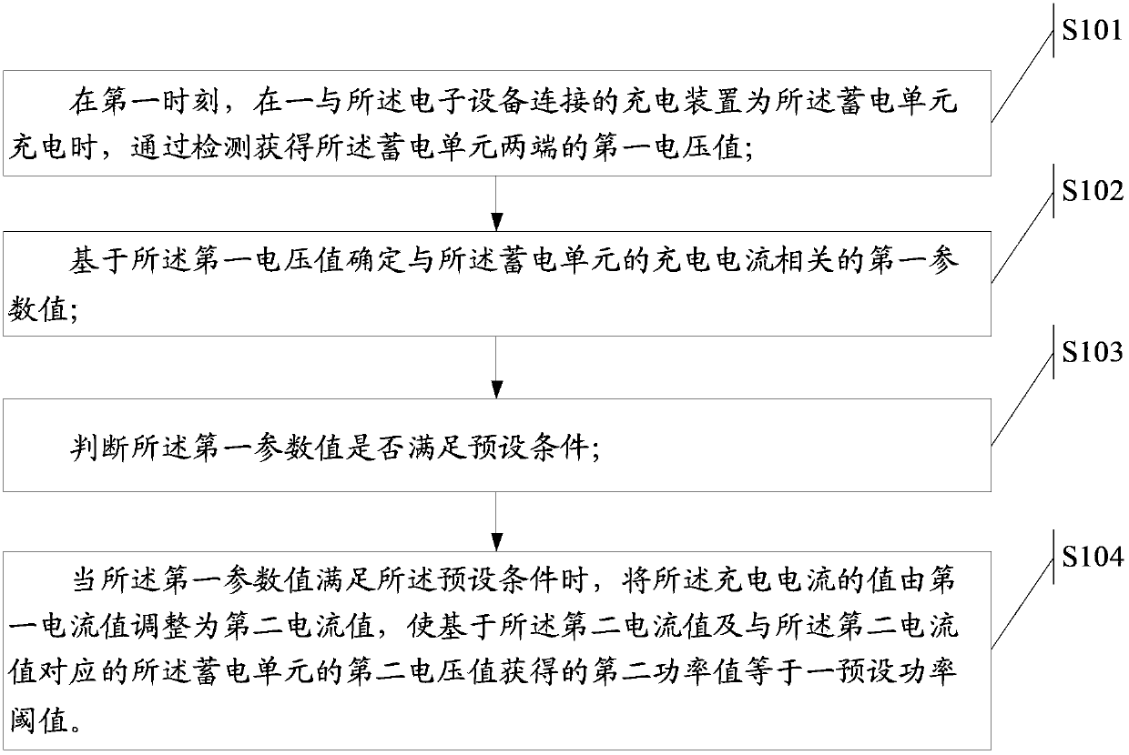
[0088] Please refer to figure 1 , The charging method includes the following steps:

[0089] Step S101: At the first moment, when a charging device connected to the electronic device charges the power storage unit, obtain a first voltage value across the power storage unit through detection;

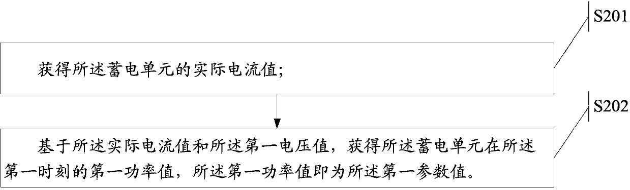
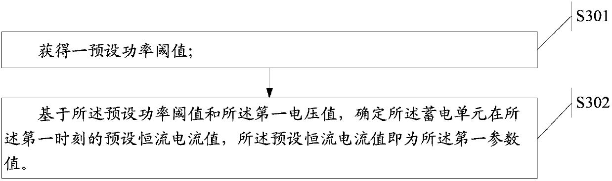
[0090] Step S102: Determine a first parameter value related to the charging current of the power storage unit based on the first voltage value;

[0091] Step S103: Determine whether the first parameter value meets a preset condition;

[0092] Step S104: When the first parameter value satisfies the preset condition, the value of the charging current is adjusted from the first current value to the second current value, so that the value is based on the second current value and the first...

Embodiment 2

[0143] In order to enable those skilled in the art to further understand the specific application process of the charging method in the first embodiment of the present application, the following will introduce the charging method introduced in the first embodiment of the present application based on actual operation.

[0144] In this embodiment, the charging method is applied to a laptop computer, and the laptop computer includes a power storage unit, please refer to Figure 4 , The notebook computer includes the following structure:

[0145] The system end 41, the system end 41 includes: a processor 41a, used to control the charging mode of the battery end; charger 41b, the first end 41b1 of the charger 41b is connected to a power adapter, used to Said battery chip power supply;

[0146] The battery 42 specifically includes: a battery chip 42a for storing electric energy; a power calculation unit 42b for calculating the electric energy stored in the battery chip 42a; and a protectio...

Embodiment 3

[0160] Based on the same inventive concept, the third embodiment of the present application provides an electronic device. The electronic device includes a power storage unit. The electronic device is, for example, a notebook computer, a tablet computer, and so on.


PUM


Abstract

The invention discloses a charging method and an electronic device. The charging method is applied to an electronic device which includes an electric storage unit. The method includes: at a first moment, when a charging device which is connected with the electronic device charges the electric storage unit, a first voltage value at the two ends of the electric storage unit is obtained through detection; based on the first voltage value, a first parameter value related with a charging current of the electric storage unit is determined; whether the first parameter value satisfies a preset condition is judged; when the first parameter value satisfies the preset condition, the value of the charging current is adjusted form a first current value to a second current value so that a second power value which is obtained on the basis of the second current value and a second voltage value of the electric storage unit corresponding to the second current value is equal to a preset power threshold.

Description

Technical field [0001] The present invention relates to the field of electronic technology, in particular to a charging method and electronic equipment. Background technique [0002] With the development of global information technology, electronic equipment products have completely penetrated people's lives. Many electronic equipment products, such as notebooks, mobile phones, PADs, etc., have become widely popular tools due to their portable characteristics, bringing more and more convenience to users. [0003] Among them, these electronic devices all need a power supply to supply power. In the prior art, a constant current and constant voltage charging mode is usually used for charging. In the initialization phase, the power supply unit is charged in a constant current mode. At this stage, the power of the power supply unit increases linearly with time, and its voltage value also increases until its voltage value reaches the preset voltage upper limit; Perform constant voltage...

Claims


Application Information

Patent Timeline
IPC IPC(8): H02J7/00
Inventor 赵双成李涛
Owner LENOVO (BEIJING) CO LTD
Why Eureka
Try Eureka