Two-dimensional linear air float guide rail type mechanical arm gravity compensation device

An air-floating guide rail and gravity compensation technology, which is applied to manipulators, manufacturing tools, etc., can solve the problems of drive motors not operating normally, damage to manipulators, etc., and achieve the effects of easy understanding and implementation, simple mechanism, and little influence of deformation

Active Publication Date: 2014-06-25
HARBIN INST OF TECH
View PDF7 Cites 7 Cited by
  • Summary
  • Abstract
  • Description
  • Claims
  • Application Information

AI Technical Summary

Problems solved by technology

[0003] In order to solve the problem that the space manipulator is related to the weightless environment of space, if the gravity compensation is not performed in the ground test, the driving motor will not operate normally, or even damage the manipulator, and then a two-dimensional linear air-floating guide rail type manipulator is proposed. Gravity compensation device

Method used


Image

  • Two-dimensional linear air float guide rail type mechanical arm gravity compensation device
  • Two-dimensional linear air float guide rail type mechanical arm gravity compensation device

Examples


specific Embodiment approach 1

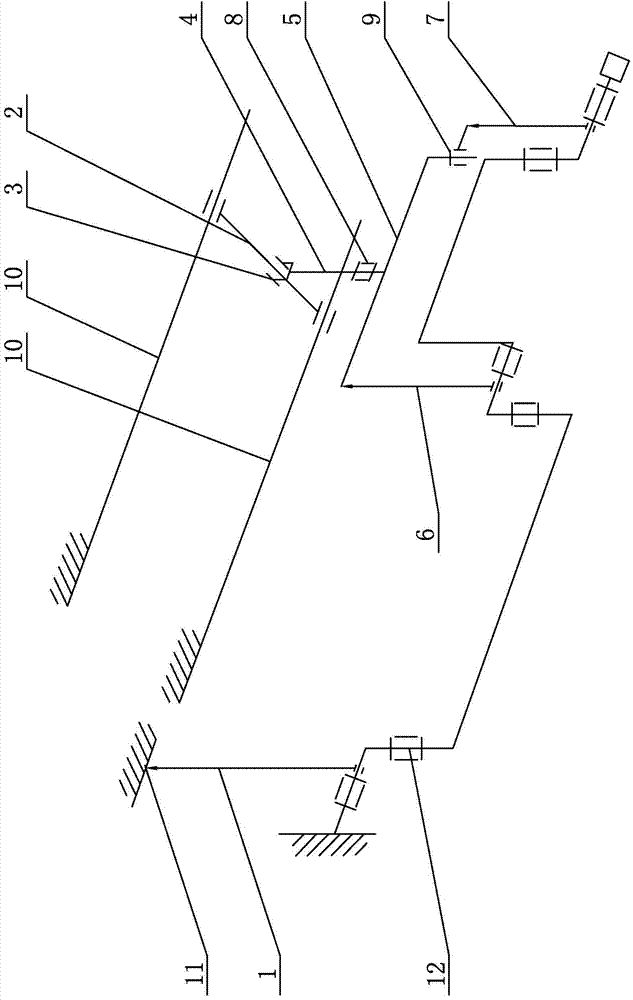
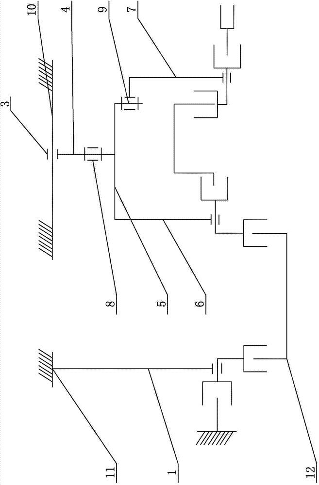
[0007] Specific implementation mode one: combine figure 1 with figure 2 Describe this embodiment, the two-dimensional linear air-floating guide rail type mechanical arm gravity compensation device in this embodiment includes a first suspension rope 1, a first linear air-floating guide rail 2, a moving slider 3, a second suspension rope 4, two Revolving hanger crossbeam 5, the 3rd suspension rope 6, the 4th suspension rope 7, the first slewing mechanism 8, the second slewing mechanism 9 and two second linear air-floating guide rails 10, the upper end of the first suspension rope 1 and the first The suspension point 11 is fixedly connected, the lower end of the first suspension rope 1 is connected to the left end of the mechanical arm 12, two second linear air-floating guide rails 10 are arranged side by side in parallel, and the first linear air-floating guide rail 2 is arranged on the two second linear air-floating guide rails. Between the guide rails 10, and the centerline ...

specific Embodiment approach 2

[0008] Specific implementation mode two: combination figure 1 with figure 2 This embodiment will be described. The upper end of the first suspension rope 1 of the two-dimensional linear air bearing guide rail type manipulator gravity compensation device in this embodiment is connected to the first suspension point 11 through a fixed air bearing.

[0009] The technical effect of this embodiment is: set in this way, the upper end of the first suspension rope 1 is fixedly connected through the air bearing, so that the position of the left end of the mechanical arm 12 does not change, so the first suspension rope 1 remains vertical all the time, the first suspension The zero gravity compensation can be realized when the rope 1 is fixed. Other components and connections are the same as those in the first embodiment.

[0010] working principle

[0011] The upper end of the first suspension rope 1 is fixedly connected by an air bearing, so that the position of the left end of the...


PUM


Abstract

The invention relates to a mechanical arm gravity compensation device, in particular to a two-dimensional linear air float guide rail type mechanical arm gravity compensation device which solves the problem that a space mechanical arm is designed according to a space weightless environment ball, if gravity compensation is not carried out in a ground experiment, a drive motor can not normally operate, and even the mechanical arm is damaged. According to the two-dimensional linear air float guide rail type mechanical arm gravity compensation device, the upper end of a first suspension rope is fixedly connected with a first suspension center, two second linear air float guide rails are arranged side by side in parallel, a first linear air float guide rail is arranged between the two second linear air float guide rails, the two ends of the first linear air float guide rail are in sliding connection with the two second linear air float guide rails respectively, the upper end of a second suspension rope is connected with the first linear air float guide rail through a movable sliding block, the lower end of a third suspension rope is connected with the middle portion of a mechanical arm, and the lower end of a fourth suspension rope is connected with the right end of the mechanical arm. The two-dimensional linear air float guide rail type mechanical arm gravity compensation device is used for space mechanical arm gravity compensation.

Description

technical field [0001] The invention relates to a gravity compensation device for a mechanical arm, in particular to a two-dimensional linear air-floating guide rail type gravity compensation device for a mechanical arm. Background technique [0002] The space manipulator sub-mechanism is an important part of the space robot mechanism. In the laboratory development stage, the function verification and kinematic algorithm verification of the manipulator should be carried out. The installation of the manipulator and the satellite body should be realized in the final assembly yard. After installation, the function of the manipulator and the motion accuracy of the manipulator should be tested. The above process must be completed on the ground, and the manipulator is designed according to the requirements of the weightless environment in space. In the ground test, if gravity compensation is not performed, the effect of gravity will generate large forces and moments on each joint,...

Claims


Application Information

Patent Timeline
Patent Type & Authority Applications(China)
IPC IPC(8): B25J19/00
Inventor 邓宗全高海波刘振李楠丁亮项升
Owner HARBIN INST OF TECH
Why Eureka
Try Eureka