Changeable air intake manifold of engine and control method thereof

An intake manifold and control method technology, applied in engine control, engine components, combustion engine and other directions, can solve the problems of complex structure, uneven power output, complicated control program design of control mechanism, etc. Transient control, the effect of improving transient response performance

Inactive Publication Date: 2014-06-25
HITACHI AUTOMOTIVE SYST SUZHOU
View PDF1 Cites 6 Cited by
  • Summary
  • Abstract
  • Description
  • Claims
  • Application Information

AI Technical Summary

Problems solved by technology

However, on the one hand, the above scheme still uses the first valve and the second valve with open and closed states, and there is a problem of uneven power output when switching; on the other hand, since the variable intake passage is provided with a rotating inner cylinder, the device The overall structure is complex, and the control needs to control the opening and closing of the first valve and the second valve and the rotation angle of the inner cylinder separately, which also leads to the complexity of the setting of the control mechanism and the design of the control program

Method used


Image

  • Changeable air intake manifold of engine and control method thereof
  • Changeable air intake manifold of engine and control method thereof
  • Changeable air intake manifold of engine and control method thereof

Examples


Embodiment

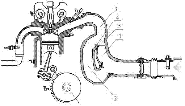
[0038] Example: see attached figure 1As shown, a variable intake manifold of an engine has a first intake passage 1 and a second intake passage 2, the length of the second intake passage 2 is greater than the length of the first intake passage 1, and the first intake passage The outlets of the first intake passage 1 and the second intake passage 2 are arranged adjacently and converge to the outlet 3 of the variable intake manifold. A valve plate 4 is hinged on the wall 5, and a valve plate driving mechanism is provided, and the valve plate driving mechanism drives the valve plate 4 to rotate according to the working conditions of the engine.

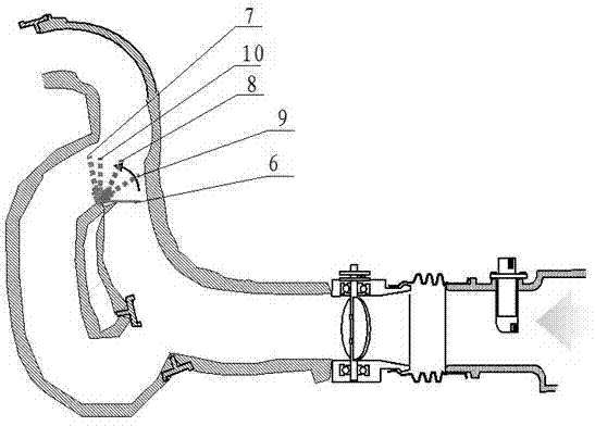
[0039] See attached figure 2 As shown, in this embodiment, the valve plate 4 has the following working positions, respectively, the first working position 6 for closing the outlet of the first air intake passage 1, and the second working position 7 for closing the outlet of the second air intake passage 2 , the third working position ...


PUM


Abstract

The invention discloses a changeable air intake manifold of an engine and a control method of the changeable air intake manifold. The changeable air intake manifold is provided with a first air intake channel and a second air intake channel, wherein the second air intake channel is longer than the first air intake channel. The changeable air intake manifold is characterized in that an outlet of the first air intake channel and an outlet of the second air intake channel are arranged adjacent to each other and converge to an outlet of the changeable air intake manifold, valve plates are hinged to the adjacent pipe walls of the outlet end of the first air intake channel and the outlet end of the second air intake channel, a valve plate driving mechanism is arranged, and the valve plate driving mechanism drives the valve plates to rotate according to working conditions of the engine. The air intake flux can be controlled by controlling the positions of the valve plates. Through the changeable air intake manifold, the transient response performance of the engine is promoted, and the changeable air intake manifold is simple in structure and convenient to control.

Description

technical field [0001] The invention relates to a part of an engine, in particular to a variable intake manifold of the engine and a control method for the variable intake manifold. Background technique [0002] The intake manifold is located between the throttle valve and the intake valve of the engine, corresponding to the number of engine cylinders. After passing through the throttle valve, the air is buffered and shunted by the intake manifold and introduced into each cylinder. The speed of the engine is different, and the amount of air required is different. In order to improve the power performance of the engine, the variable intake manifold (Variable Intake Manifold, VIM) technology is used in the prior art. Generally, intake passages of different lengths are used to realize the length control of the variable intake manifold. Use a long intake pipe to increase the torque output of the engine, and use a short intake pipe at high speed to improve the power output of th...

Claims


Application Information

Patent Timeline
Patent Type & Authority Applications(China)
IPC IPC(8): F02M35/104F02D9/02
CPCY02T10/12
Inventor 裴建龙
Owner HITACHI AUTOMOTIVE SYST SUZHOU
Why Eureka
Try Eureka