Optical-coupling lens and an optical-fiber coupling connector

A fiber coupling and optical coupling technology, which is applied in the coupling of optical waveguides, etc., can solve problems such as waste and achieve the effect of avoiding waste

Inactive Publication Date: 2014-06-25
HONG FU JIN PRECISION IND (SHENZHEN) CO LTD +1
View PDF4 Cites 0 Cited by
  • Summary
  • Abstract
  • Description
  • Claims
  • Application Information

AI Technical Summary

Problems solved by technology

However, since the optical coupling lens is integrally formed by injection molding, even if only a part of the optical coupling lens is damaged, the staff have to replace the entire optical coupling lens, resulting in a lot of waste

Method used


Image

  • Optical-coupling lens and an optical-fiber coupling connector
  • Optical-coupling lens and an optical-fiber coupling connector
  • Optical-coupling lens and an optical-fiber coupling connector

Examples


Embodiment Construction

[0016] The embodiments of the present invention will be further described in detail below in conjunction with the accompanying drawings.

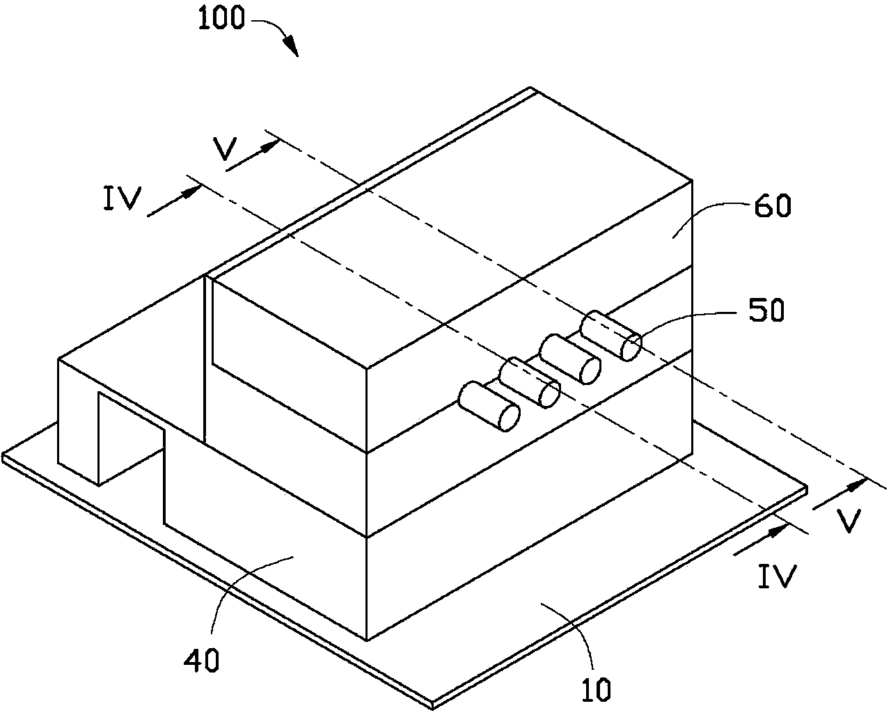
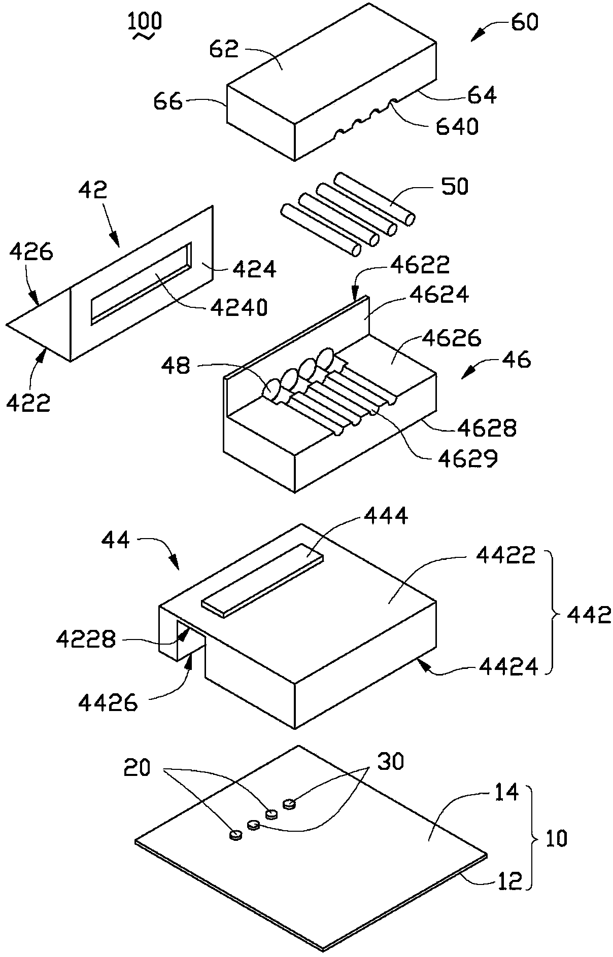
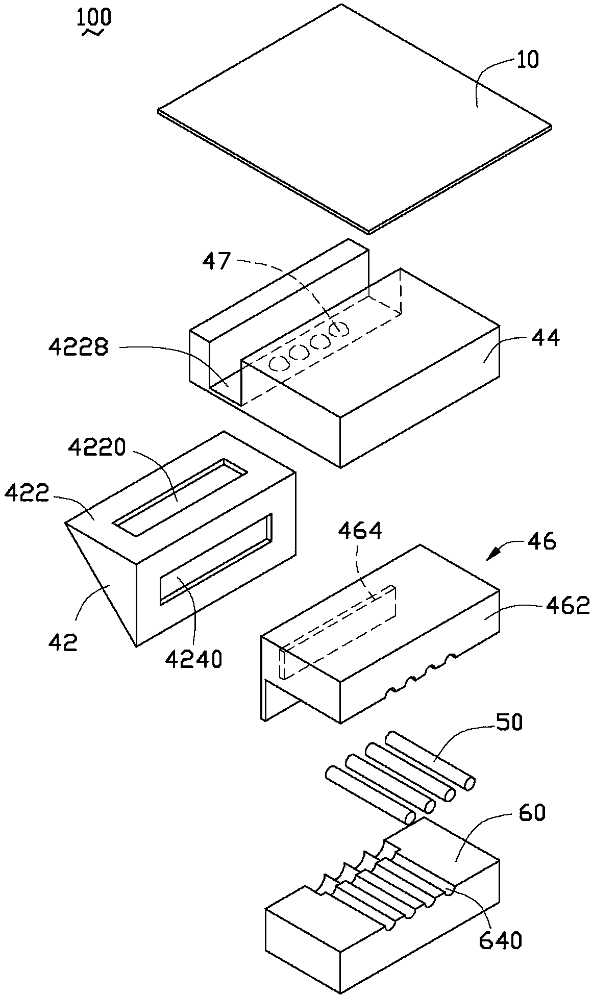
[0017] Please also refer to figure 1 and figure 2 , is the optical fiber coupling connector 100 provided by the embodiment of the present invention. The fiber coupling connector 100 includes a circuit board 10 , two light emitting modules 20 , two light receiving modules 30 , an optical coupling lens 40 , four optical fibers 50 and a cover 60 .

[0018] Please also refer to figure 2 and image 3 , the circuit board 10 includes a bottom surface 12 and a top surface 14 . The bottom surface 12 and the top surface 14 are located on opposite sides of the circuit board 10 , and the bottom surface 12 is parallel to the top surface 14 .

[0019] The two light-emitting modules 20 and the two light-receiving modules 30 are fixed on the top surface 14 and are electrically connected to the circuit board 10 . Specifically, the two light emitting...


PUM


Abstract

The invention relates to an optical coupling lens which includes a reflection part, a first installation part, a second installation part, at least one first convergent lens and at least one second convergent lens. The reflection part includes a first face, a second face vertical to the first face and a reflection face connected slantly both with the first face and the second face. The first installation part includes a first optical face. The first convergent lenses are arranged on the first optical face. The first installation part is detachably installed on the first face and enables the first optical face to be away from and parallel with the first face. The second installation part includes a second optical face. The second convergent lenses are arranged on the second optical face and are in one-to-one correspondence to the first convergent lenses. The second installation part is detachably installed on the second face and enables the second optical face to be away from and parallel with the second face. The reflection face reflects light converged by the first convergent lenses to a corresponding second convergent lens and reflects light converged by the second convergent lenses to a corresponding first convergent lens. The invention also relates to an optical-fiber coupling connector.

Description

technical field [0001] The invention relates to the field of Universal Serial Bus (USB), in particular to an optical coupling lens and an optical fiber coupling connector with the optical coupling lens. Background technique [0002] At present, the use of optical signals to transmit data is gradually applied to the USB field of personal computers, and the specific form is reflected in the use of optical fiber coupling connectors. Optical fiber coupling connectors usually include a light emitting module, an optical coupling lens, an optical fiber, and a light receiving module. Wherein, the optical coupling lens is integrally formed by injection molding, and the optical coupling lens reflects light and changes it by 90 degrees when coupling between the light-emitting module and the optical fiber or between the optical fiber and the light-receiving module. [0003] When assembling or transporting the optical fiber coupling connector, the optical coupling lens is easily damaged...

Claims


Application Information

Patent Timeline
IPC IPC(8): G02B6/42
Inventor 洪毅
Owner HONG FU JIN PRECISION IND (SHENZHEN) CO LTD
Why Eureka
Try Eureka