CUSP magnetic field generator coil and processing method thereof

A magnetic field generating device and coil technology, which is applied in coils, coil manufacturing, chemical instruments and methods, etc., can solve the problems of affecting the service life of CUSP magnetic field devices, difficult processing, easy deformation, etc., and achieve shortening of waterway distance and manufacturing process arrangement Reasonable, high yield effect

Active Publication Date: 2014-06-25
ZHEJIANG JINGSHENG MECHANICAL & ELECTRICAL +1
View PDF8 Cites 2 Cited by
  • Summary
  • Abstract
  • Description
  • Claims
  • Application Information

AI Technical Summary

Problems solved by technology

[0002] The processing and production of the coil in the CUSP magnetic field generator is one of the key points and difficulties. At present, the coil is mostly made of hollow square copper tubes directly, which has the disadvantages of difficult processing, easy deformation, and easy damage, which affects the performance of the CUSP magnetic field generator. service life

Method used


Image

  • CUSP magnetic field generator coil and processing method thereof
  • CUSP magnetic field generator coil and processing method thereof
  • CUSP magnetic field generator coil and processing method thereof

Examples


Embodiment Construction

[0045] The following examples can make those skilled in the technical field understand the present invention more comprehensively, but do not limit the present invention in any way.

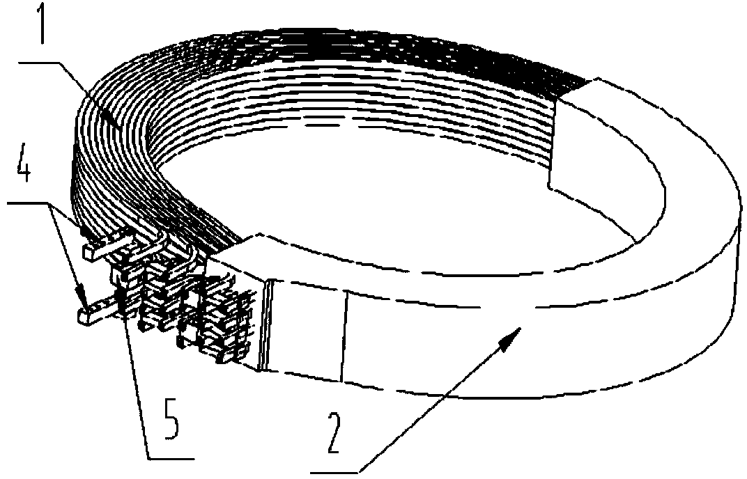
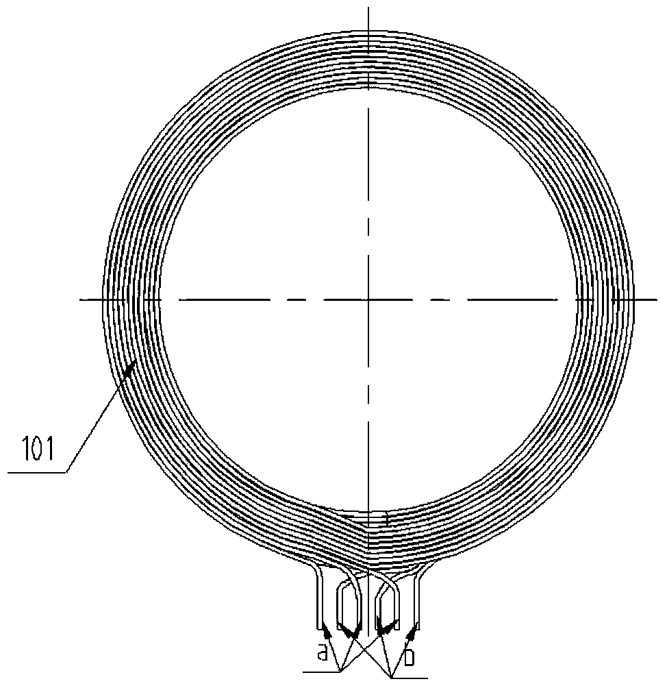
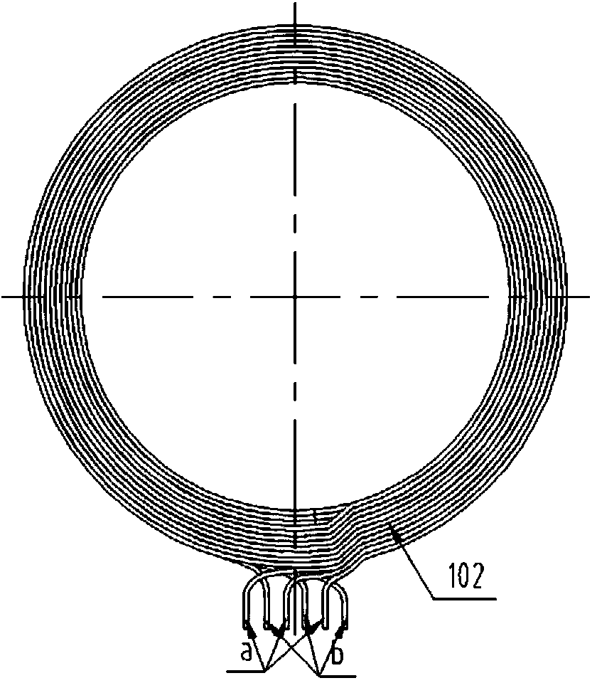
[0046] figure 1 Shown in is a schematic diagram of a coil with 8 axial turns and 10 radial turns. For the convenience of understanding, only half of the epoxy resin 2 is shown. figure 2 and image 3 are schematic diagrams of coil unit I101 and coil unit II102 respectively, Figure 4 A schematic diagram of the cross-section of the coil.

[0047]The present invention provides a coil of a CUSP magnetic field generating device, comprising a cylindrical coil group 1 wound by a copper tube 1011, one side of the coil group 1 is provided with a water inlet and outlet, an epoxy resin 2, an insulating plate 3, an electrode 4, The connection block 5; the insulating plate 3 is arranged between the copper pipes 1011, and the epoxy resin 2 is cast to cover the entire coil group 1; the connection block 5 an...


PUM


Abstract

The invention relates to nonmetal crystal manufacturing equipment, and aims to provide a CUSP magnetic field generator coil and a processing method thereof. The CUSP magnetic field generator coil comprises a cylindrical coil assembly wound by copper tubes, a water inlet and outlet end, epoxy resin, insulating plates, electrodes and connectors are arranged on one side of the coil assembly, the insulating plates are arranged between the copper tubes, and the epoxy resin covers the integral coil assembly in a casting manner; the connectors and the electrodes are arranged at the water inlet and outlet end of the coil assembly. The CUSP magnetic field generator coil has the advantages that the coil manufacturing technology is reasonable in arrangement, and industrialized production yield is high; the coil is wound by the optimized copper tubes and integrally cast by the epoxy resin and is good in thermal stability; by parallel winding coil units via multiple copper tubes, waterway distance of a single copper tube is shortened, and temperature rise of the coil is low; the winding requirement of the coil that any radial turns and axial turns are the multiple of four can be met, and more flexible options are provided for optimized design of the coil.

Description

technical field [0001] The invention relates to non-metallic crystal manufacturing equipment, in particular to a coil of a CUSP magnetic field generator and a processing method thereof. Background technique [0002] The processing and production of the coil in the CUSP magnetic field generator is one of the key points and difficulties. At present, the coil is mostly made of hollow square copper tubes directly, which has disadvantages such as difficult processing, easy deformation, and easy damage, which affects the performance of the CUSP magnetic field generator. service life. Contents of the invention [0003] The technical problem to be solved by the present invention is to overcome the deficiencies in the prior art and provide a coil of a CUSP magnetic field generator and a processing method thereof. [0004] For solving technical problem, solution of the present invention is: [0005] A CUSP magnetic field generating device coil is provided, including a cylindrical ...

Claims


Application Information

Patent Timeline
Patent Type & Authority Applications(China)
IPC IPC(8): H01F5/00H01F41/04C30B30/04
Inventor 曹建伟欧阳鹏根汤承伟傅林坚朱亮
Owner ZHEJIANG JINGSHENG MECHANICAL & ELECTRICAL
Why Eureka
Try Eureka