Misoperation preventing device of equipment emergency switch

An anti-misoperation device and emergency switch technology, applied in emergency protection devices, parts of protection switches, protection switches, etc., can solve problems such as economic losses, power failure of users or related lines, and emergency unlocking buttons are not allowed to be activated, etc. To achieve the effect of preventing huge damage

Inactive Publication Date: 2014-06-25
STATE GRID CORP OF CHINA +1
View PDF5 Cites 3 Cited by
  • Summary
  • Abstract
  • Description
  • Claims
  • Application Information

AI Technical Summary

Problems solved by technology

However, during normal operation, the emergency unlock button is not allowed to be activated, otherwise, once the circuit breaker is opened, it will cause a power outage for users or related lines, causing serious economic losses
In the prior art, when the equipment leaves the factory, the button has no anti-mistouch measures. Therefore, during the daily operation and maintenance process, the circuit breaker is likely to be opened due to accidental touches by operators or tools.

Method used


Image

  • Misoperation preventing device of equipment emergency switch
  • Misoperation preventing device of equipment emergency switch
  • Misoperation preventing device of equipment emergency switch

Examples


Embodiment 1

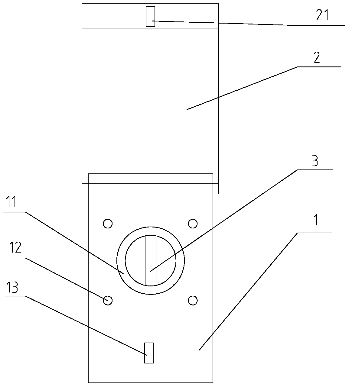
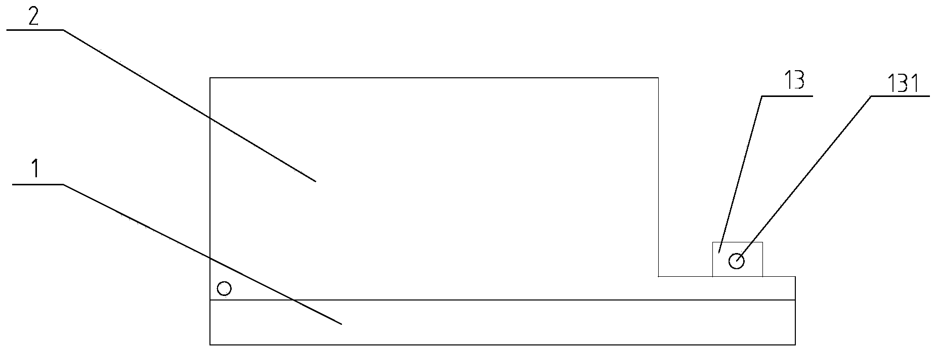
[0025] refer to figure 1 with image 3 , shows an anti-misoperation device for an emergency switch of equipment, including a mounting plate 1 connected to the outer wall of the equipment, on which a protective cover 2 is detachably connected, and the anti-misoperation device is positioned on On the equipment casing, after the protective cover 2 is connected to the mounting plate 1, the emergency switch 3 of the equipment is separated from the outside.

[0026] Preferably, the mounting plate 1 is provided with screw holes 12, the mounting plate 1 is mounted on the outer wall of the equipment by screws, the bottom surface of the mounting plate 1 is close to the outer wall of the equipment, the protective cover 2 is connected to the surface of the mounting plate 1, and the mounting plate 1 is also provided with a through hole 11, and the equipment emergency switch 3 is located in the protective cover 2 after passing through the through hole 11. Alternatively, the mounting plate...

Embodiment 2

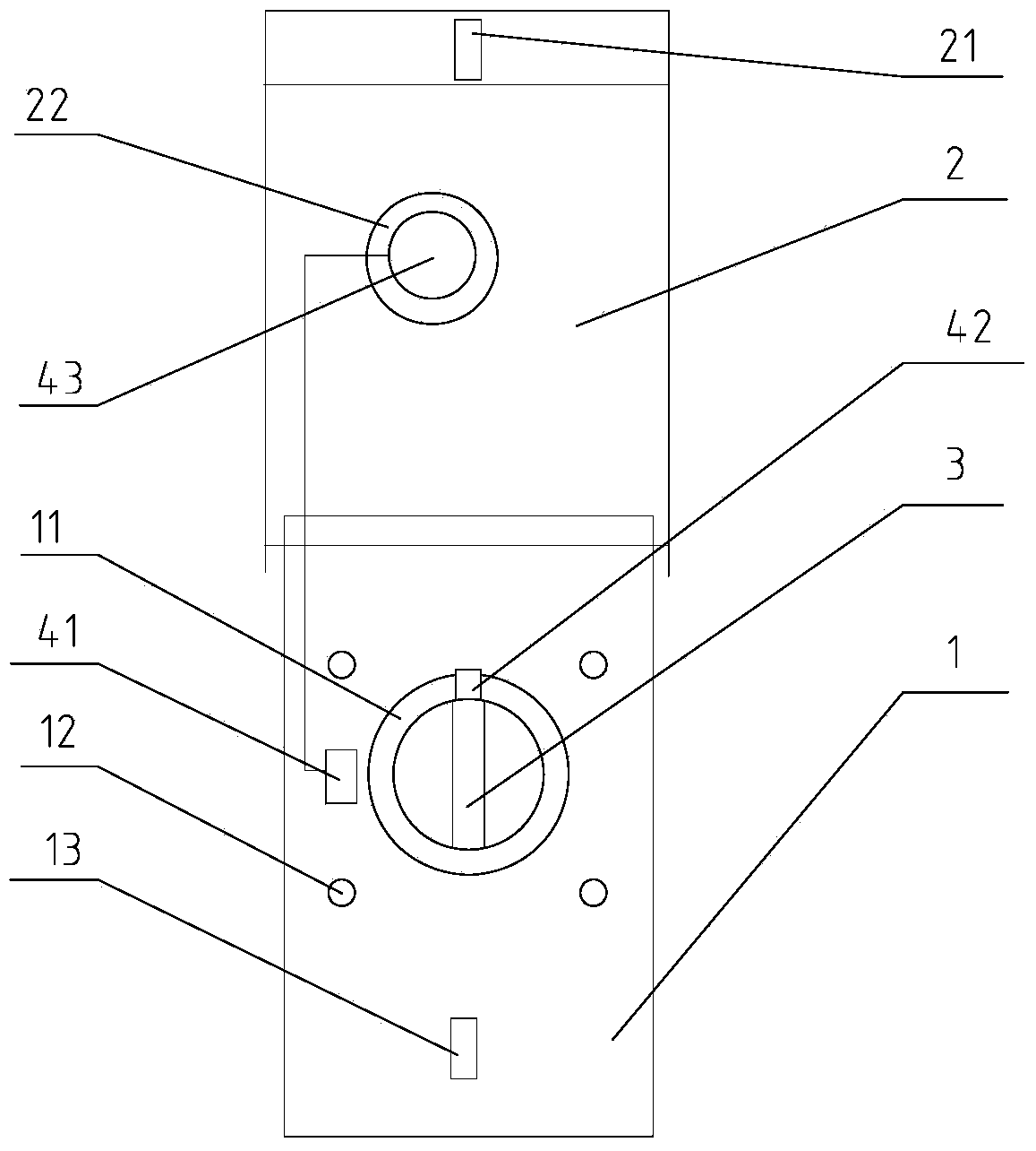
[0032] refer to figure 2 , on the basis of Embodiment 1, the anti-misoperation device also includes an indicator light 43 and a power supply module, the power supply module includes a storage battery connected in series with the indicator light, and the series circuit includes a static contact 41 arranged on the mounting plate 1 and assembled on the The movable contact 42 on the emergency switch 3 of the equipment. After an emergency occurs, start the emergency switch 3 of the equipment. After the emergency switch 3 of the equipment is in an emergency closed state, the moving contact 42 will contact the static contact 41 to conduct the circuit, and the power supply module supplies power to the indicator light 43 . For example: when the emergency switch 3 of the equipment is a knob, the movable contact 42 is a piece connected to the rotary shaft of the knob, and the static contact 41 is a clamping seat fixed on the mounting plate 1, and the rotation of the knob drives the mova...


PUM


Abstract

The invention discloses a misoperation preventing device of an equipment emergency switch, relating to the field of power equipment. A technical problem that the easy misoperation of an equipment emergency switch causes a huge economic loss in the prior art is solved. The misoperation preventing device comprises an installation plate which is connected to the outer wall of equipment, the installation plate is connected with a protection cover, and the equipment emergency switch is in the protection cover. The misoperation preventing device is applied to the field of power equipment.

Description

【Technical field】 [0001] The invention relates to an auxiliary device for electrical equipment, in particular to an anti-misoperation device for electrical equipment. 【Background technique】 [0002] The switchgear equipment in the power system is equipped with an emergency unlock button. In an emergency, pressing the emergency unlock button can immediately open the circuit breaker in the equipment, thereby protecting the safety of people, equipment, and the power grid. However, during normal operation, the emergency unlock button is not allowed to be activated, otherwise, once the circuit breaker is opened, it will cause a power outage for users or related lines, causing serious economic losses. In the prior art, when the equipment leaves the factory, the button has no anti-mistouch measures. Therefore, in the process of daily operation and maintenance, the circuit breaker is likely to be opened due to accidental touches by operators or tools. 【Content of invention】 [00...

Claims


Application Information

Patent Timeline
Patent Type & Authority Applications(China)
IPC IPC(8): H01H71/02
Inventor 归宇席俞佳高奥凌秋阳殷文宣陈昱王涤沈竹源
Owner STATE GRID CORP OF CHINA
Why Eureka
Try Eureka