Check patentability & draft patents in minutes with Patsnap Eureka AI!

A metal electromigration structure

An electromigration and metal technology, applied in circuits, electrical components, electro-solid devices, etc., can solve problems such as failure of the connecting metal layer 3

Active Publication Date: 2016-08-17
SHANGHAI HUALI MICROELECTRONICS CORP
View PDF5 Cites 0 Cited by
  • Summary
  • Abstract
  • Description
  • Claims
  • Application Information

AI Technical Summary

Problems solved by technology

[0003] At present, this situation is avoided by increasing the width of the connection metal layer 3, but since the applied current is conducted to the connection metal layer 3 through the interconnection line 2, the connection metal layer 3 under the interconnection line 2 Still prone to failure point 5

Method used


Image

  • A metal electromigration structure
  • A metal electromigration structure
  • A metal electromigration structure

Examples


Embodiment Construction

[0015] The specific embodiment of the present invention will be further described below in conjunction with accompanying drawing:

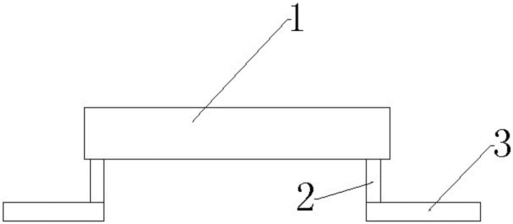
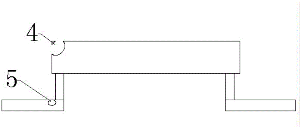
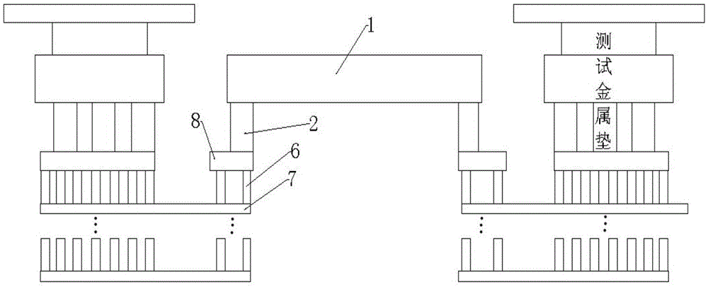
[0016] A metal electromigration structure, the metal electromigration structure includes: a test metal layer 1, a transition metal layer 8, a first interconnection 2, a second interconnection 6, and a connection structure; the two ends of the test metal layer 1 are respectively Connected to a transition metal layer 8 through an interconnection line 2, each transition metal layer 8 is also connected to a connection structure through at least two second interconnection lines 6, wherein the thickness of each transition metal layer 8 is less than 1 μm, The connection structure is a plurality of connection metal layers 7 connected in series through the second interconnection line 6. The metal electromigration structure also includes two metal pads, and each metal pad is connected to the test metal layer 1 through a connection structure for testing The ...


PUM

PropertyMeasurementUnit
thicknessaaaaaaaaaa

Abstract

The invention relates to the field of semiconductor manufacturing, in particular to a metal electromigration structure. Top connection metal layers serve as transition layers, the mode of lower connection metal layers is added, so that the transition metal layers do not generate transverse currents, in this way, currents flowing towards the lower layers in the transition metal layers can not generate electromigration easily due to the fact that the distance is too short (smaller than 1 micrometer), meanwhile, due to the fact that the lower connection metal layers are not limited by the number of interconnection lines, enough interconnection line shunt currents can be added, stress concentration points are effectively prevented from occurring on the lower connection metal layers , and then the probability that electromigration failure points are located on the connection metal layers is reduced.

Description

technical field [0001] The invention relates to the field of semiconductor manufacturing, in particular to a metal electromigration structure. Background technique [0002] In the manufacture of integrated circuits, it is necessary to test the electromigration performance of different metal layers. The test structure is shown in the transverse cross-sectional view of the electromigration test structure ( figure 1 ): 1 is the metal layer to be tested, 2 is the interconnection line (according to the requirements, there can only be one at each end), and 3 is the connecting metal layer. However, in some processes, it is often encountered that the thickness of each metal layer is different, and sometimes the difference in thickness (H) between two adjacent metal layers can reach 3 times or even greater. At this time, when the current stress (I) is applied to the metal layer under test, the current density (J, J=I / s, s is the cross-sectional area of ​​the metal) borne by the conn...

Claims


Application Information

Patent Timeline
Patent Type & Authority Patents(China)
IPC IPC(8): H01L23/544
Inventor 尹彬锋钱燕妮于赫薇
Owner SHANGHAI HUALI MICROELECTRONICS CORP
Features
  • R&D
  • Intellectual Property
  • Life Sciences
  • Materials
  • Tech Scout
  • Unparalleled Data Quality
  • Higher Quality Content
  • 60% Fewer Hallucinations
Learn More