Heating furnace and cleaning method inside the heating furnace

A heating furnace and hearth technology, applied in the field of heating furnace, can solve the problems of reduced operating efficiency, large heat loss, high equipment cost, etc., and achieve the effect of shortening downtime and efficient cleaning

Inactive Publication Date: 2016-04-06
CHUGAI RO CO LTD
View PDF7 Cites 0 Cited by
  • Summary
  • Abstract
  • Description
  • Claims
  • Application Information

AI Technical Summary

Problems solved by technology

[0005] However, there is a problem that it takes a long time to stop the operation of the heating furnace and sufficiently cool the inside of the heating furnace, and it takes a long time to sufficiently raise the temperature in the heating furnace to restart the operation of the heating furnace. for a long time, resulting in a significant reduction in operating efficiency
[0007] However, when the descaling conveyor and the descaling recovery unit are installed on the self-propelled trolley in this way, the self-propelled trolley will be enlarged, and in the hearth provided with a large number of pillars supporting various beams, There was a problem that the pillars installed on the hearth were obstructed, and the self-propelled trolley could not be moved properly, and the oxide scale etc. accumulated on the hearth could not be sufficiently removed.
[0009] However, when a hopper inclined downward is provided with respect to the entire hearth, a scale discharge pipe is continuously provided under the hopper, and the lower end of the scale discharge pipe is dipped in a water tank for water sealing. In this case, the structure of the inside of the heating furnace becomes complicated, and its construction becomes very difficult, and there are problems that the equipment cost is very high.
In addition, there are many problems such as the heat in the heating furnace is guided to the water tank through the hopper and the scale discharge pipe installed so as to penetrate the hearth, and the heat loss is very large.

Method used


Image

  • Heating furnace and cleaning method inside the heating furnace
  • Heating furnace and cleaning method inside the heating furnace
  • Heating furnace and cleaning method inside the heating furnace

Examples


Embodiment Construction

[0030] Hereinafter, a heating furnace according to an embodiment of the present invention and a method of cleaning the inside of the heating furnace will be specifically described with reference to the drawings. In addition, the heating furnace and the cleaning method in the heating furnace of the present invention are not limited to the cases shown in the following embodiments, and can be appropriately changed and implemented within the scope of not changing the idea of ​​the invention.

[0031] In this embodiment, a walking beam type heating furnace is described as an example, but the heating furnace of the present invention is not limited to a walking beam type heating furnace, and can be applied to various types of heating furnaces such as a pusher type.

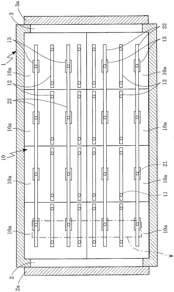
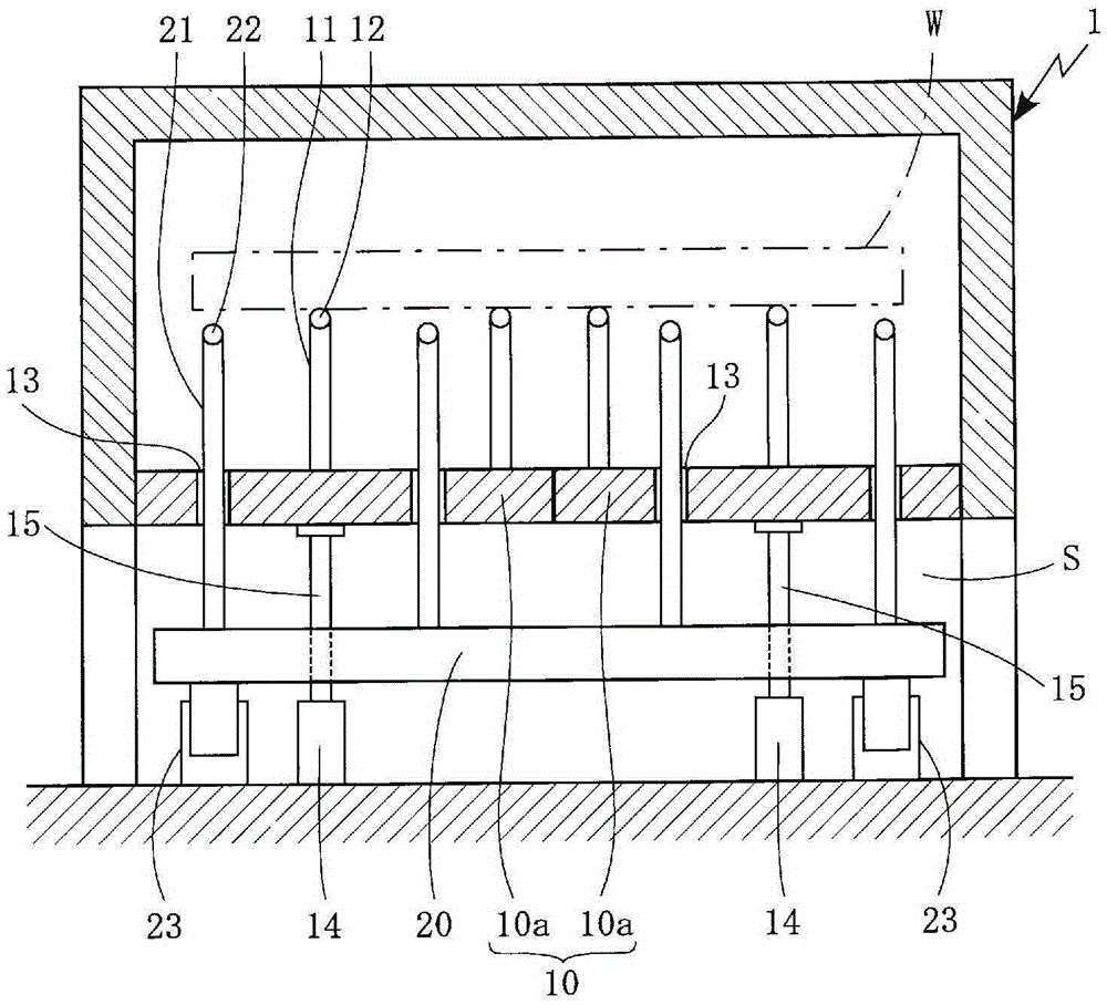
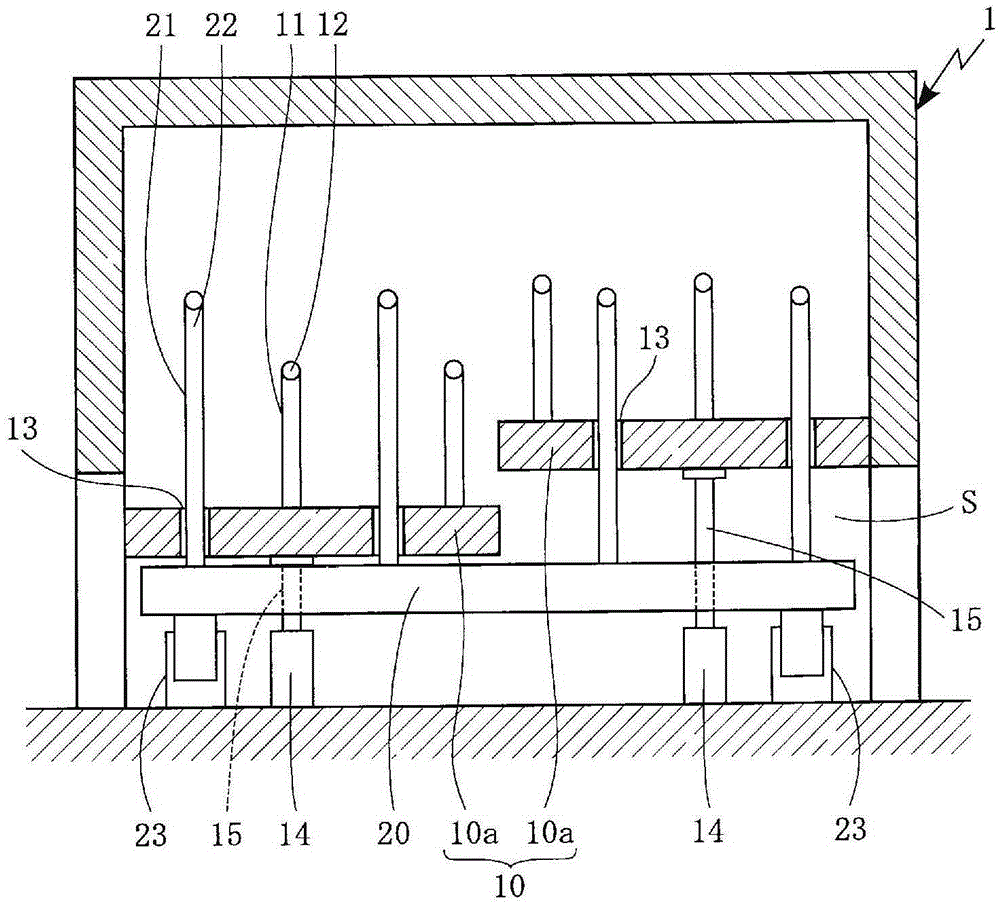
[0032] In the walking beam type heating furnace 1 of this embodiment, as figure 1 and figure 2 As shown, on the hearth 10 provided in the heating furnace 1, a plurality of support members 11 are erected at required int...


PUM


Abstract

For a heating furnace for which the hearth is supported by means of hearth support pillars provided in a space below the hearth, the present invention addresses the problem of efficiently and quickly removing scale and the like generated in the heating furnace and accumulating on the hearth, without providing complex equipment in the heating furnace. In this heating furnace (1), for which the hearth (10) is supported by means of hearth support pillars (15) provided in a space (S) below the hearth, the hearth is divided into multiple sections, and at least a portion of the hearth support pillars supporting the resulting hearth sections (10a) are provided with elevation devices (14). The hearth sections are raised or lowered via the hearth support pillars by means of these elevation devices, thereby forming vertical gaps between adjacent hearth sections, and the interior of the heating furnace is cleaned by way of these gaps.

Description

technical field [0001] The present invention relates to a heating furnace in which a hearth is supported by hearth pillars provided in a space below the hearth, and a cleaning method for cleaning the inside of the heating furnace. In particular, it is characterized in that, when removing scales and the like generated in the heating furnace and deposited on the hearth, the deposits can be efficiently removed in a short time without complicating the structure of the inside of the heating furnace and the like. Clean scales, etc. on the hearth. Background technique [0002] Conventionally, various types of heating furnaces, such as walking beam type and pusher type, are used as heating furnaces for sequentially moving objects to be processed such as steel sheets and steel plates within the heating furnace to perform heat treatment continuously. [0003] Here, in the above-mentioned heating furnace, in general, when the object to be processed is conveyed sequentially in the heat...

Claims


Application Information

Patent Timeline
Patent Type & Authority Patents(China)
IPC IPC(8): F27B9/24F27B3/06F27B9/30F27D99/00
CPCF27B9/24F27B9/30
Inventor 山本俊辅
Owner CHUGAI RO CO LTD
Why Eureka
Try Eureka