Machining system and robot system

A processing system and robot technology, applied in the direction of metal processing machinery parts, metal processing, general control system, etc., can solve the problems of not being able to improve processing efficiency, achieve high-speed processing, improve processing efficiency, high-precision and processing effects

Inactive Publication Date: 2018-03-16
FANUC LTD
View PDF1 Cites 8 Cited by
  • Summary
  • Abstract
  • Description
  • Claims
  • Application Information

AI Technical Summary

Problems solved by technology

However, it is necessary to stop the machine tool when cleaning and replacing the processed workpiece, and it is necessary to stop the robot that processes the workpiece during the processing of the workpiece, so there is a problem that the processing efficiency cannot be improved.

Method used


Image

  • Machining system and robot system
  • Machining system and robot system
  • Machining system and robot system

Examples


Embodiment Construction

[0050] Next, a processing system 1 according to an embodiment of the present invention will be described with reference to the drawings.

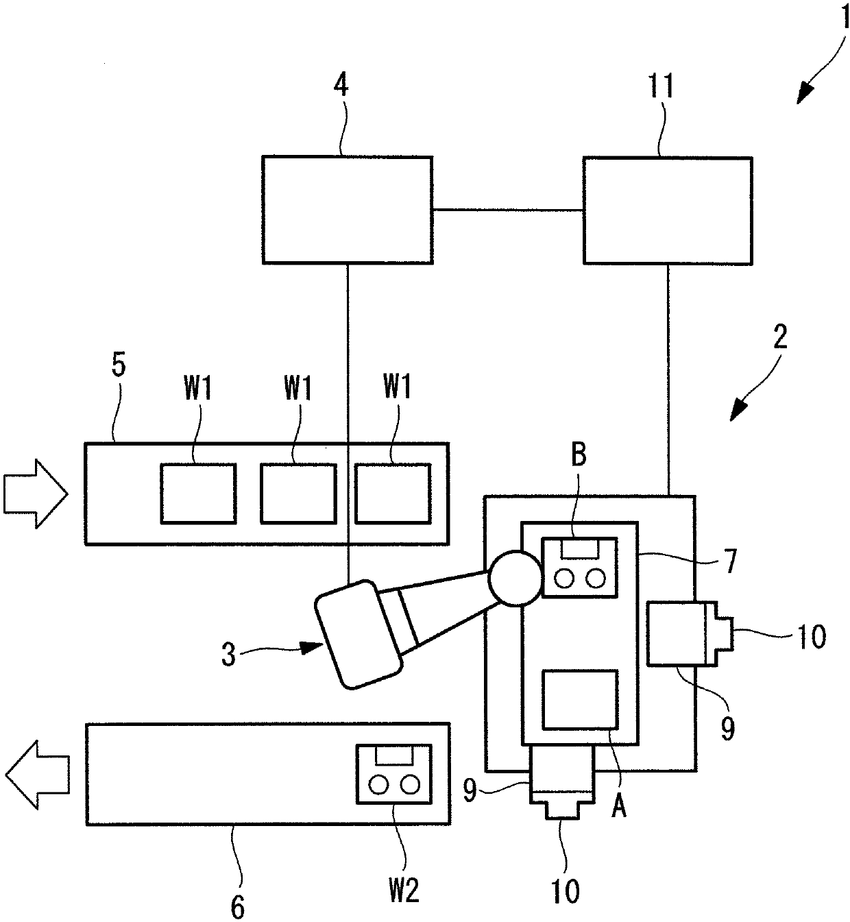
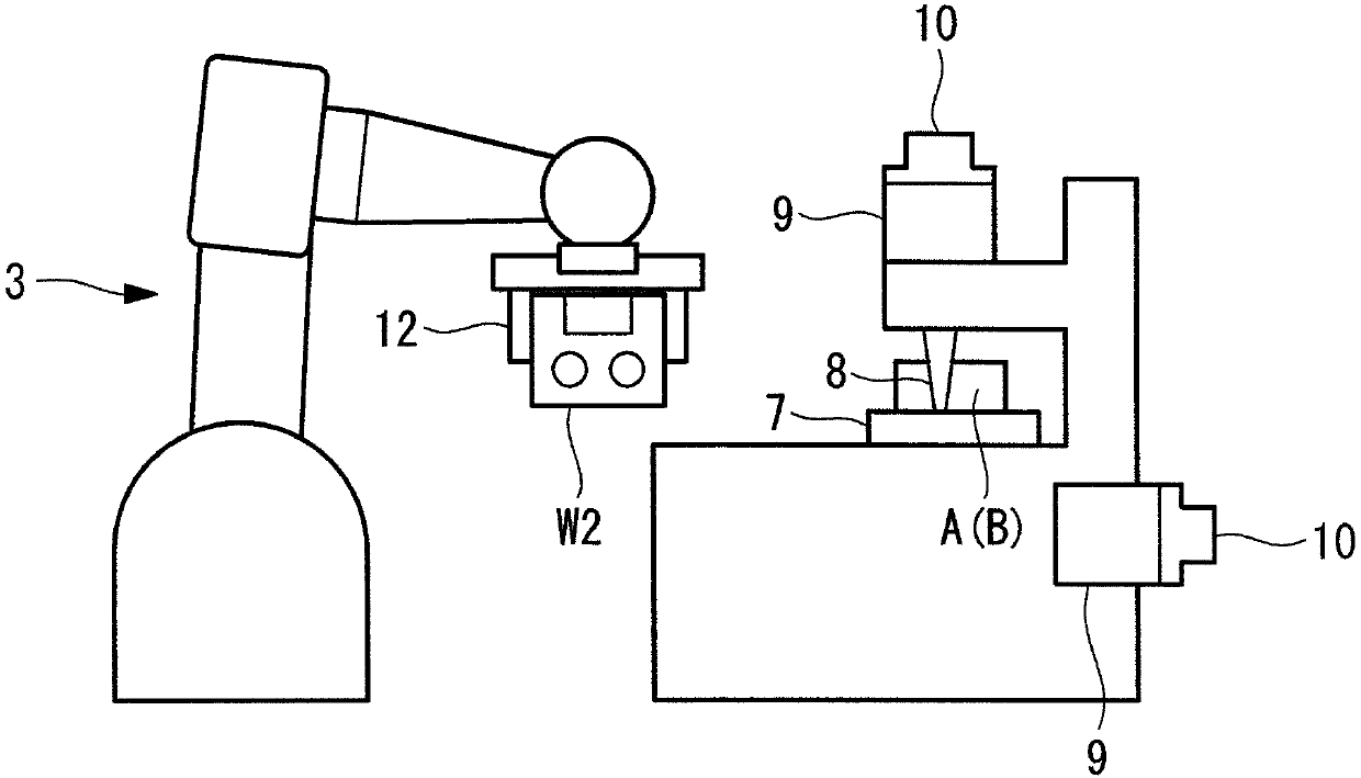
[0051] The processing system 1 of the present embodiment is as figure 1 As shown, it includes: a machine tool 2, a robot 3, a robot control device (robot control unit) 4 for controlling the robot 3, a supply conveyor 5 for supplying an unprocessed workpiece W1, and a sending conveyor for sending out a processed workpiece W2. 6.

[0052] like figure 1 as well as figure 2As shown, the machine tool 2 is equipped with: a worktable 7, which fixes the workpiece W1 on the upper surface and moves the workpiece W1 in two horizontal directions; a tool shaft 8, which moves a tool such as a drill bit up and down along a vertical axis and makes the The drill blade rotates around the vertical axis; the motor 9 drives the table 7 and the tool shaft 8; the encoder 10 detects the rotation angle of each motor 9; 10 detected rotation angle to control eac...


PUM


Abstract

The invention provides a machining system and a robot system, and there is an advantage in machining efficiency that can be greatly improved by reducing waiting time of the robot and the machine toolfor the machine tool capable of achieving a high machining feed rate and high machining accuracy. There is provided a machining system (1) including: a machine tool (2) that moves a table (7) on whicha plurality of works (A), (B) are fixed, in a two-dimensional manner, to machine the one work (A) by driving a blade shaft in a direction orthogonal to a moving direction of the table (7); a robot (3) that is disposed at a position accessible to the table (7) of the machine tool (2) to apply processing to the other one work (B) fixed to the table (7); and a robot control unit (4) that controls the robot (3) so as to follow movement of the table (7) on the basis of position information on the table (7).

Description

technical field [0001] The invention relates to machining systems as well as robotic systems. Background technique [0002] Conventionally, a machining system is known that includes a machine tool that fixes a plurality of workpieces on a stationary machining table and performs machining by moving a tool shaft relative to the workpieces. In the machining system, using a tool While processing, the processed workpiece is cleaned, or the processed workpiece is taken out by a robot and replaced with an unprocessed workpiece (for example, refer to Patent Document 1). [0003] prior art literature [0004] patent documents [0005] Patent Document 1: Japanese Patent Laid-Open No. 2009-297861 Contents of the invention [0006] The problem to be solved by the invention [0007] However, in the machining system described in Patent Document 1, it is usually necessary to move a heavy tool shaft, and there is a problem that machining accuracy and machining speed cannot be improved...

Claims


Application Information

Patent Timeline
Patent Type & Authority Applications(China)
IPC IPC(8): B23Q37/00B23Q1/25B25J9/08
CPCB23Q1/25B23Q37/00B25J9/08G05B19/41825G05B2219/39105G05B2219/39145B25J11/005B23Q7/007B23Q7/04Y02P90/02B25J11/0055G05B19/402G05B2219/40243
Inventor 奥园清隆滝川隆士
Owner FANUC LTD
Why Eureka
Try Eureka