Braking system and method for braking a vehicle in the event of abrupt changes of the friction coefficient

A friction coefficient, wheel brake technology, applied in the direction of brake transmission, brakes, vehicle components, etc., can solve problems such as uneconomical cost, uncontrollable vehicles, instability, etc., to shorten the stopping time of wheels, small load, negative pressure Level up effect

Inactive Publication Date: 2013-07-31
ROBERT BOSCH GMBH
View PDF5 Cites 7 Cited by
  • Summary
  • Abstract
  • Description
  • Claims
  • Application Information

AI Technical Summary

Problems solved by technology

The vehicle is known to lose control or become unstable in such conditions
In principle it is possible to enlarge the storage chamber or the return pump, but this is uneconomical and therefore unpopular for cost reasons

Method used


Image

  • Braking system and method for braking a vehicle in the event of abrupt changes of the friction coefficient
  • Braking system and method for braking a vehicle in the event of abrupt changes of the friction coefficient
  • Braking system and method for braking a vehicle in the event of abrupt changes of the friction coefficient

Examples


Embodiment Construction

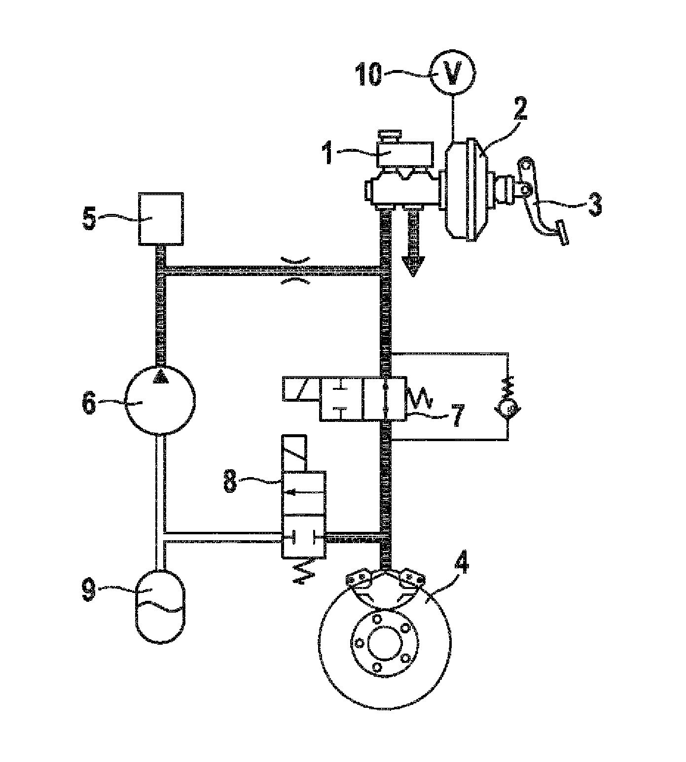
[0017] Figure 1 shows a typical brake circuit of a hydraulic brake system with ABS function. The brake circuit comprises a master brake cylinder 1 having a container for hydraulic fluid arranged thereon. The brake booster 2 is coupled to the brake pedal 3 and boosts the braking force applied by the driver.

[0018] The brake pressure developed on the master brake cylinder 1 is conducted via the inlet valve 7 to the wheel brakes 4 . The outlet valve 8 arranged on the output of the wheel brake 4 is closed in this state.

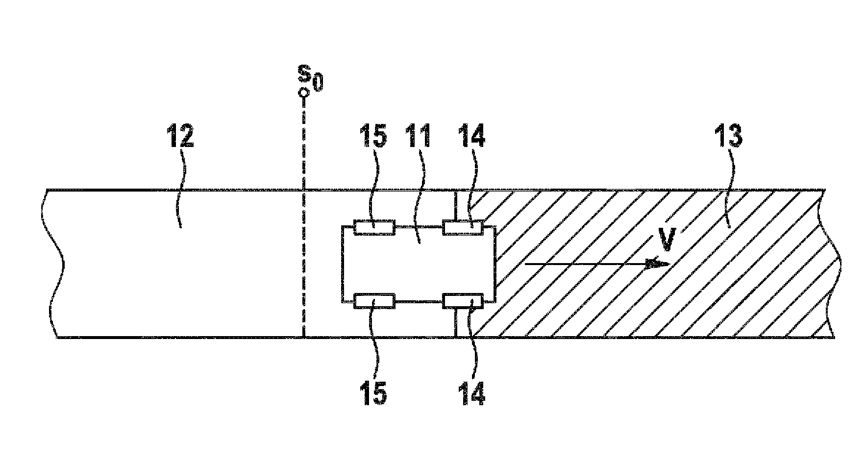
[0019] FIG. 2 shows a vehicle 11 driving at a speed v on a road surface with different coefficients of friction. The road surface comprises an area 12 with a higher coefficient of friction μ, such as asphalt, and an area 13 with a lower coefficient of friction μ, such as snow or ice. The vehicle 11 is at location s 0 During the braking process that has already started.

[0020] In the position shown, the vehicle 11 with the front wheels 14 is directly at t...


PUM


Abstract

A brake device is described for braking the wheels of a vehicle. The brake device includes at least one brake master cylinder, a brake booster, a wheel brake, a return pump, using which a hydraulic fluid may be pumped back from the wheel brake in the direction of brake master cylinder. A sensor system for detecting an abrupt negative change in the friction coefficient of the roadway is provided. An arrangement is provided according to which the boost of the brake booster is set to a smaller value if a braking maneuver has been detected on a roadway having an abrupt negative change in the friction coefficient than in the case of a braking maneuver on a roadway without an abrupt negative change in the friction coefficient.

Description

technical field [0001] The invention relates to a braking system for a vehicle with improved braking performance in driving situations in which the vehicle brakes on a road surface with an unfavorable jump in the coefficient of friction , and the invention relates to a method for braking a vehicle in a corresponding driving situation. Background technique [0002] Various brake control systems are known from the prior art, such as ABS (Anti-lock Brake System), ASR (Anti-Slip Control) or ESP (Electronic Stability Program), by means of which brake control systems can be prevent wheel locking. These systems generally monitor wheel slip by means of wheel speed sensors. If the brake control system detects excessive wheel slip at the wheel, the brake pressure in the associated wheel brake is temporarily reduced. The outlet valve is usually opened for this purpose. The brake fluid present in the wheel brakes then flows through the outlet valve into a storage chamber and from th...

Claims


Application Information

Patent Timeline
Patent Type & Authority Applications(China)
IPC IPC(8): B60T8/1764B60T8/40B60T8/50B60T13/66
CPCB60T13/146B60T2210/124B60T8/1764B60T8/172B60T13/66B60T8/1763B60T8/505B60T8/3265B60T13/686B60T13/72B60T8/404B60T8/448B60T8/4275
Inventor R.布吕格曼A.赖策P.弗吕
Owner ROBERT BOSCH GMBH
Why Eureka
Try Eureka