Computer system, method, and program

a computer system and program technology, applied in the field of techniques, can solve the problems of no particular solution for reducing the system stop time, system stops when the system configuration is changed, etc., and achieve the effects of reducing the program stop time, reducing the idle time, and reducing the cos

Active Publication Date: 2013-04-25
IBM CORP
View PDF46 Cites 8 Cited by
  • Summary
  • Abstract
  • Description
  • Claims
  • Application Information

AI Technical Summary

Benefits of technology

[0016]According to the present invention, program shutdown time when shifting from the stream program in the present phase to the next phase can be reduced by gradually shifting empty tasks in the present phase to the next stream program as alternative tasks in consideration of the cost of switching between tasks, the cost of transferring data among resources, and so on.
[0017]At that time, the alternative tasks are selected by measuring and storing, in advance, the pipeline pitches of related tasks, a related-task switching cost, and a cost including the time for data transmission and reception between the resources in the related phases so that the costs are reduced in consideration of the present phase and the next phase, the transition of resources used, and the transition of tasks executed.
[0018]According to the present invention, a computer-controlled dynamic resource assignment system is provided with the advantage of reducing a program stop time when shifting from the original configuration to the next configuration depending on the circumstances by reducing an idle time between processes by selecting alternative tasks from the original configuration to execute an intermediate process.

Problems solved by technology

Although these prior arts disclose techniques for changing system configuration by changing performance on the server and improving the processing capacity depending on the result, they have a problem in that the system stops when the system configuration is changed.
However, the related arts suggest no particular solution for reducing the system stop time during switching the system configuration.

Method used


Image

  • Computer system, method, and program
  • Computer system, method, and program
  • Computer system, method, and program

Examples


Embodiment Construction

[0040]An embodiment of the present invention will be described hereinbelow with reference to the drawings. The same reference numerals denote the same components throughout the drawings unless otherwise specified. It is to be understood that the following description is an embodiment of the present invention and that the invention is not limited to the description of the embodiment.

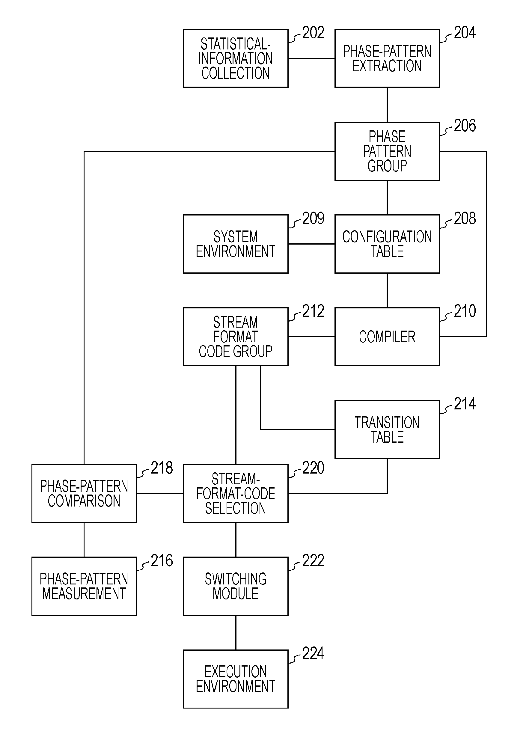
[0041]FIG. 1 is a block diagram showing a hardware configuration for performing the present invention. This embodiment uses a multicore multiprocessor router appliance 100, such as a PRISM; however, the present invention is not limited thereto.

[0042]In FIG. 1, a bus 102 is connected to a multicore processor 104, a multicore processor 106, a RAM 108, an Ethernet stack & Ethernet port 110, and a flash ROM 112.

[0043]Examples of the multicore processors 104 and 106 include a network processor, such as an Intel® IXP 425 network processor, although not limited thereto. The network processor has the functions of...


PUM


Abstract

Traffic data while the system is in operation is collected for a certain time as a preprocess. Typical patterns are extracted from the collected traffic data. Next, stream programs are created for the individual typical patterns and stored for the future reference. Next, the IDs of alternative tasks for transition among different stream programs are stored. In actual system operation, the system measures traffic data regularly or at any time, compares the resultant patterns with the typical patterns, and selects a stream program corresponding to the closest typical pattern as the next phase. Program shutdown time when shifting from the stream program in the present phase to the next phase can be reduced by gradually shifting empty tasks in the present phase to the next stream program as alternative tasks in consideration of the cost of switching between tasks, the cost of transferring data among resources, and so on.

Description

TECHNICAL FIELD[0001]The present invention relates to a technique for dynamically assigning resources in a computer system depending on the state of network traffic and so on, and more specifically, it relates to a technique for switching the configuration of resource assignment.BACKGROUND ART[0002]Hitherto, dynamic change of resource assignment has been performed to optimize computer processing depending on the operating state of active application programs and the state of network traffic. For that purpose, the following techniques are proposed.[0003]Japanese Unexamined Patent Application Publication Nos. 2005-174201 and 2007-48315 disclose a resource assignment change system that includes a resource list including a server, a network, and a storage; an application list showing the components of applications operating on the resources; an resource-application assignment list; a performance information measurement item template that generates performance information measurement ite...

Claims


Application Information

Patent Timeline
Patent Type & Authority Applications(United States)
IPC IPC(8): H04L12/26
CPCH04L43/04G06F9/485
Inventor DOI, MUNEHIROKOMATSU, HIDEAKIMAEDA, KUMIKOMURASE, MASANAYOSHIZAWA, TAKEO
Owner IBM CORP
Why Eureka
Try Eureka