Photon counting detector

A detector array and discriminator technology, applied in instruments, measuring devices, scientific instruments, etc., can solve problems such as unacceptable time

Active Publication Date: 2014-06-25
KONINKLJIJKE PHILIPS NV
View PDF5 Cites 9 Cited by
  • Summary
  • Abstract
  • Description
  • Claims
  • Application Information

AI Technical Summary

Problems solved by technology

Unfortunately, the time required to perform a threshold sweep can be unacceptable, especially when performing system calibration

Method used


Image

  • Photon counting detector
  • Photon counting detector
  • Photon counting detector

Examples


Embodiment Construction

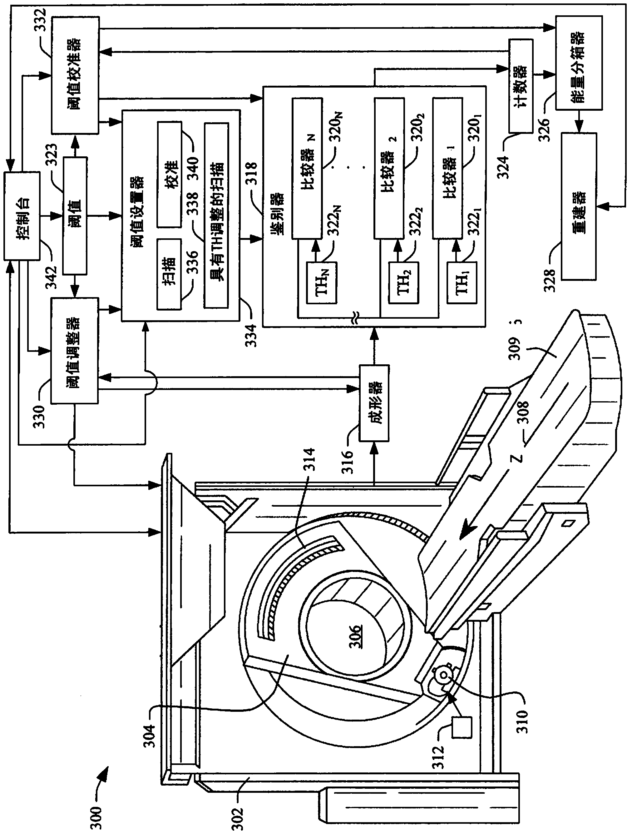
[0022] first reference image 3 , schematically shows an imaging system 300 such as a computed tomography (CT) scanner.

[0023] The imaging system 300 includes a fixed gantry 302 and a rotating gantry 304 rotatably supported by the fixed gantry 302 . Rotating gantry 304 rotates about examination region 306 about longitudinal or z-axis 308 .

[0024] A subject support 309 such as a couch supports a subject or subject in the examination area 306 . The subject support 309 can be used to position the subject or subject vertically and / or horizontally relative to the imaging system 300 before, during and / or after scanning.

[0025]A radiation source 310 , such as an x-ray tube, is supported by and rotates with rotating gantry 304 about examination region 306 about longitudinal or z-axis 308 . Radiation source 310 emits concentrated energy ionizing radiation that is collimated by a collimator or the like to generate a generally fan-shaped, wedge-shaped, or cone-shaped radiation b...


PUM


Abstract

An imaging system (300) includes a detector array (314)with direct conversion detector pixels that detect radiation traversing an examination region of the imaging system and generate a signal indicative of the detected radiation, a pulse shaper (316) configured to alternatively process the signal indicative of detected radiation generated by the detector array or a set of test pulses having different and known heights that correspond to different and known energy levels and to generate output pulses having heights indicative of the energy of the processed detected radiation or set of test pulses, and a thresholds adjuster (330); configured to analyze the heights of the output pulses corresponding to the set of test pulses in connection with the heights of set of test pulses and a set of predetermined fixed energy thresholds and generate a threshold adjustment signal indicative of a baseline based on a result of the analysis.

Description

technical field [0001] The following generally relates to photon counting detectors and is described with a particular application to computed tomography (CT); however, the following applies to other imaging modalities as well. Background technique [0002] Computed tomography (CT) scanners generally include a rotating gantry rotatably mounted to a stationary gantry. The rotating gantry supports the X-ray tube and is configured to rotate around the examination region about the longitudinal direction. The detector array is arranged opposite to the X-ray tube across the inspection area. The x-ray tube is configured to emit concentrated energy ionizing radiation that traverses the examination region (and the object or portion of the subject within it) and illuminates the detector array. A detector array includes a one-dimensional or two-dimensional array of detector pixels that detect radiation and generate a signal indicative of the radiation. Each pixel is associated with ...

Claims


Application Information

Patent Timeline
Patent Type & Authority Applications(China)
IPC IPC(8): G01T1/24G01T7/00
CPCH05G1/26G01T1/24G01T1/247G01T7/005G01N23/046G01T1/17G01T1/2985
Inventor R·斯特德曼布克R·P·卢赫塔C·赫尔曼
Owner KONINKLJIJKE PHILIPS NV
Why Eureka
Try Eureka