Hydraulic damp-adjustable rotating buffer
A technology of hydraulic damping and buffer, which is applied in the field of hydraulic damping buffer, can solve the problems of the buffer occupying a large cover plate assembly space, which is not conducive to miniaturization design, etc., and achieves convenient assembly or adjustment, simple structure and reliable adjustment function. Effect
- Summary
- Abstract
- Description
- Claims
- Application Information
AI Technical Summary
Problems solved by technology
Method used
Image
Examples
Embodiment 1
[0033] Embodiment one (The adjustment hole runs through the axis of the shaft)
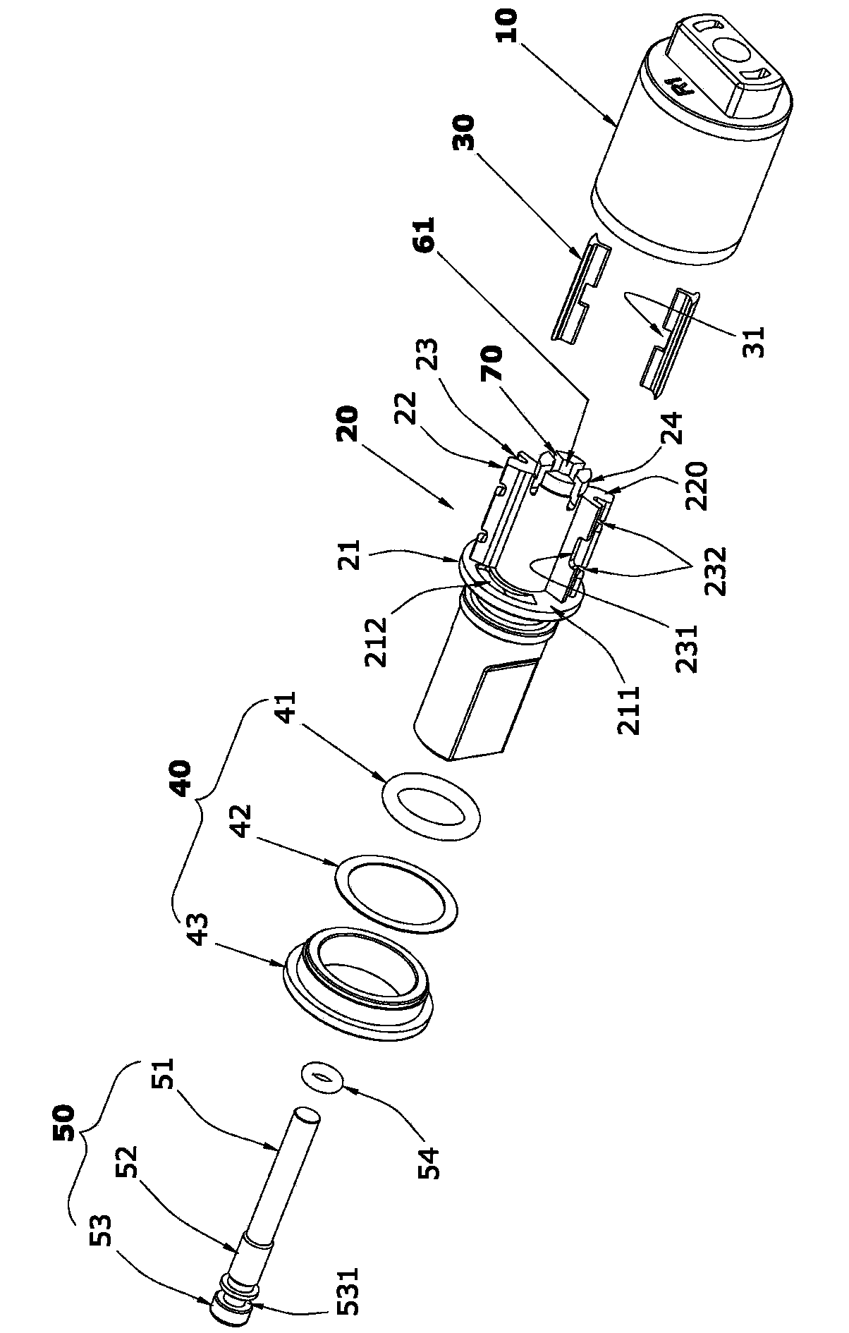
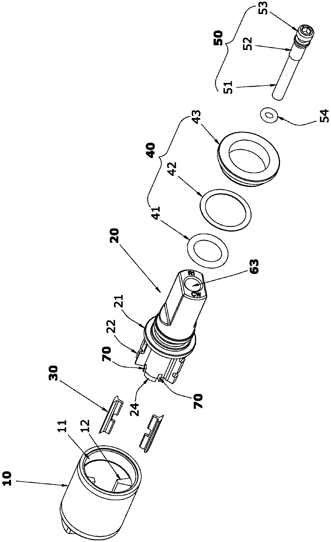
[0034] Such as figure 1 , figure 2 and Figure 10 The rotary buffer with adjustable hydraulic damping shown is mainly composed of a shaft sleeve 10 , a rotating shaft 20 , an oil-passing valve plate 30 , a sealing assembly 40 and an adjusting screw 50 .
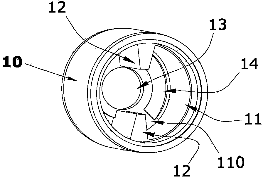
[0035] Such as figure 2 , image 3 and Figure 4 shown , The bushing inner cavity 11 of the bushing 10 of the present invention is used to support the rotation of the rotating shaft 20, and two oil-separating ribs 12 are symmetrically arranged on the wall of the bushing inner cavity 11, and the oil-separating ribs 12 extend from the opening of the inner cavity 11 Fixed to the bottom surface 110 of the inner cavity, the center of the bottom of the inner cavity 11 of the shaft sleeve is provided with a bearing hole 13 for supporting the rotation of the supporting shaft 24 at the end of the rotating shaft 20. A pair of oil un...
Embodiment 2
[0045] Embodiment two (The adjustment hole does not pass through the axial direction of the rotating shaft).
[0046] Such as Figure 12 and Figure 13 As shown, the difference between this embodiment and Embodiment 1 is that the axial rear end of the socket 61 is not arranged on the support shaft 24, the adjustment hole 60 does not penetrate to the support shaft 24, and the throttle port 70 still communicates through the socket 61. When the adjusting screw 50 makes the bottom end surface of the round bar section 51 touch the jack 61, the round bar section 51 of the adjusting screw 50 completely closes and blocks the orifice 70, so that the orifices 70 cannot communicate with each other. When the rotation speed of the rotating shaft 20 is fixed; when the adjusting screw 50 is turned to make the round bar section 51 form a gap with the bottom of the socket 61 and each throttle port 70 at the same time, each throttle port 70 is connected through the socket 61, and the ci...
PUM
 Abstract
Description
Claims
Application Information
 - R&D
- Intellectual Property
- Life Sciences
- Materials
- Tech Scout
- Unparalleled Data Quality
- Higher Quality Content
- 60% Fewer Hallucinations
Browse by: Latest US Patents, China's latest patents, Technical Efficacy Thesaurus, Application Domain, Technology Topic, Popular Technical Reports.
© 2025 PatSnap. All rights reserved.Legal|Privacy policy|Modern Slavery Act Transparency Statement|Sitemap|About US| Contact US: help@patsnap.com


