A rotary buffer with adjustable hydraulic damping

A hydraulic damping and buffer technology, which is applied in the field of hydraulic damping buffers, can solve the problems of large assembly space occupied by the cover plate of the buffer, unfavorable miniaturization design, etc., and achieve the advantages of convenient assembly or adjustment, simple structure, and reduced length Effect

Active Publication Date: 2015-12-23
HOTI XIAMEN PLUMBING ING
View PDF4 Cites 0 Cited by
  • Summary
  • Abstract
  • Description
  • Claims
  • Application Information

AI Technical Summary

Problems solved by technology

[0004] Another example is a new type of adjustable buffer disclosed in the Chinese utility model patent (CN2580897Y). The inner cavity of the cylinder body 1 is equipped with a shaft core 2, and the inner cavity of the cylinder body 1 is provided with two symmetrical support pieces 6. 2 is provided with a partition 7 and a vane 8, wherein the support 6, the partition 7 and the vane 8 divide the inner cavity into a pressurized chamber and a non-pressurized chamber. The rear part of the cylinder 1 is provided with an adjustment chamber 11. The rear end of the cylinder is provided with an adjustable back cover 12, and the pressure chamber and the non-pressure chamber in the cylinder 1 have convection holes 13 to communicate with the adjustment chamber 11; although the space of the adjustment chamber 11 is adjusted by turning the back cover 12 to adjust the convection The flow rate of the hole 13 makes the hydraulic damping force of the inner chamber of the cylinder body 1 adjustable to the shaft core 2, realizes the adjustable speed of the shaft core 2, and adjusts the buffering time of the toilet cover; the setting of the convection hole 13 requires an additional partition cylinder The partition between the inner cavity of the body 1 and the adjustment chamber 11, and the connection between the rear cover 12 and the sealing nut at the rear end of the cylinder body 1 to form the adjustment chamber 11 also increases the axial length of the buffer, so this buffer occupies the cover plate The assembly space is large, which is not conducive to the miniaturization design of the product
[0005] Another example is a Chinese utility model patent (CN202118173U) which discloses a speed-adjustable damper, which includes a shaft sleeve 20 that can be filled with damping oil, and a rotating shaft 10 that can seal and rotate with the shaft sleeve 20 and can disturb the flow of the damping oil. Between the rotating shaft 10 and the shaft sleeve 20 there is at least one one-way oil-passing valve plate 30, one end of the shaft sleeve 20 is provided with a seal 40 which can move axially to adjust the length of the inner cavity of the shaft sleeve 20, and a nut is embedded in the rotating shaft 10 50, an adjusting screw 60 passes through the sealing member 40 and is screwed to the nut 50, and the sealing member 40 cooperates with the rotating shaft 10; the sealing member 40 and the rotating shaft 20 rotate together, and the gap between them is adjusted through the screw 60. The flow pressure of the damping oil changes the damping force of the damping oil on the rotating shaft 10, so as to achieve the purpose of adjusting the rotating speed and rotation time of the rotating shaft 10; this damper is connected and linked with the sealing member 40 and the rotating shaft 10 through the screw 60, and the sealing is adjusted through the screw 60 The distance between the sealing member 40 and the rotating shaft 10 in the shaft sleeve 20 is used to adjust the oil passing speed and realize the function of speed regulation; the existing problem is that the linkage between the sealing member 40 and the rotating shaft 10 in the shaft sleeve 20 may cause the screw 60 to loosen and cause The axial distance between the seal 40 and the rotating shaft 10 is changed, and the rear end of the sleeve 20 is provided with the seal 40 to increase the length of the damper

Method used


Image

  • A rotary buffer with adjustable hydraulic damping
  • A rotary buffer with adjustable hydraulic damping
  • A rotary buffer with adjustable hydraulic damping

Examples


Embodiment 1

[0033] Embodiment 1 (the adjustment hole runs through the axis of the shaft)

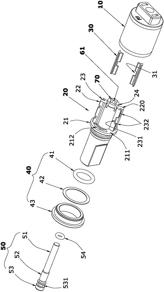
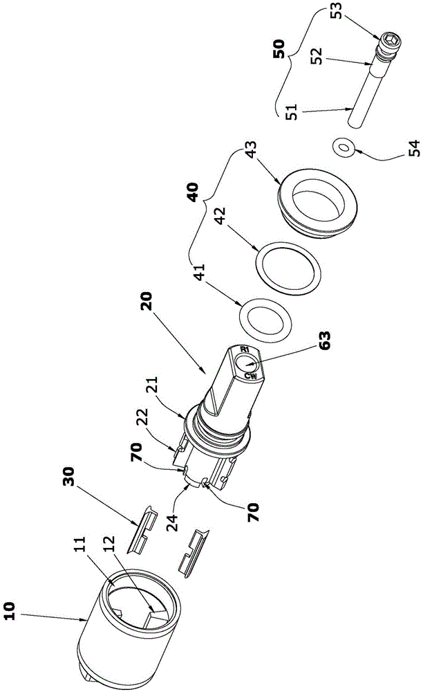
[0034] like figure 1 , figure 2 and Figure 10 The rotary buffer with adjustable hydraulic damping shown is mainly composed of a shaft sleeve 10 , a rotating shaft 20 , an oil-passing valve plate 30 , a sealing assembly 40 and an adjusting screw 50 .

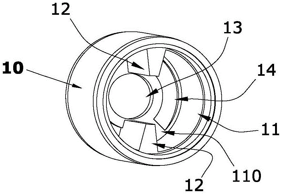
[0035] like figure 2 , image 3 and Figure 4 As shown, the shaft sleeve inner cavity 11 of the shaft sleeve 10 of the present invention is used to support the rotation of the rotating shaft 20, and the two oil-separating ribs 12 are symmetrically arranged on the wall of the shaft sleeve inner cavity 11, and the oil-separating ribs 12 are separated from the inner cavity 11. The opening extends to the bottom surface 110 of the inner cavity and is fixed. The center of the bottom of the inner cavity 11 of the shaft sleeve is provided with a bearing hole 13 for supporting the rotation of the supporting shaft 24 at the end of the rotating shaft 20. ...

Embodiment 2

[0045] Embodiment 2 (the adjustment hole does not pass through the axial direction of the rotating shaft).

[0046] like Figure 12 and Figure 13 As shown, the difference between this embodiment and Embodiment 1 is that the axial rear end of the socket 61 is not arranged on the support shaft 24, the adjustment hole 60 does not penetrate to the support shaft 24, and the throttle port 70 still communicates through the socket 61. When the adjusting screw 50 makes the bottom end surface of the round bar section 51 touch the jack 61, the round bar section 51 of the adjusting screw 50 completely closes and blocks the orifice 70, so that the orifices 70 cannot communicate with each other. When the rotation speed of the rotating shaft 20 is fixed; when the adjusting screw 50 is turned to make the round bar section 51 form a gap with the bottom of the socket 61 and each throttle port 70 at the same time, each throttle port 70 is connected through the socket 61, and the circle The...


PUM


Abstract

A rotary buffer with adjustable hydraulic damping, including a shaft sleeve that can be filled with damping oil, a rotating shaft that is sealed and rotated with the shaft sleeve and can disturb the flow of damping oil, and each of the two rotor plates of the rotating shaft is equipped with a one-way oil passage The valve plate is slidingly matched with the inner cavity wall of the shaft sleeve. There are two oil barrier ribs on the inner cavity wall of the shaft sleeve that conflict with the rotating shaft and limit the rotation range of the rotor plate. A supporting shaft is provided at the rear end of the rotating shaft and a A bearing hole fits in the shaft; an adjusting hole is provided in the axial direction of the rotating shaft from front to rear, and an adjusting screw is inserted into the adjusting hole from the front end of the rotating shaft and sealed with it; the rotating shafts on both sides of each rotor plate are provided with a connecting sleeve in the radial direction The throttling port of the inner cavity and the regulating hole can be adjusted by turning the regulating screw to adjust the oil passage gap between it, the throttling port and the regulating hole. Since the adjusting screw is fixed in the rotating shaft, the adjusting screw is not used for positioning or supporting the rotating shaft, so the length of the present invention is greatly reduced, the structure is simpler, and the assembly or adjustment is more convenient and reliable.

Description

technical field [0001] The invention relates to a hydraulic damping buffer for a toilet cover, in particular to a rotary buffer with adjustable hydraulic damping. Background technique [0002] At present, most toilet covers use hydraulic damping buffers to adjust the rotation speed of the cover, so as to realize the functions of quick lifting and slow closing of the cover. The adjustment mechanisms of the existing hydraulic damping buffers are all set This design is not conducive to the miniaturization of the buffer, and the adjustment mechanism may be displaced due to external contact during assembly, or the adjustment accuracy may be affected by the rotation of the shaft during work, resulting in mass production. The speed of the buffer is inconsistent, which causes the cover plate to vibrate due to the different left and right torque when it is rotated and turned down for buffering, and the cover plate buffer is not stable enough. [0003] For example, a damper disclosed...

Claims


Application Information

Patent Timeline
Patent Type & Authority Patents(China)
IPC IPC(8): A47K13/04
Inventor 陈国斌
Owner HOTI XIAMEN PLUMBING ING
Why Eureka
Try Eureka