Rotary buffer with adjustable damping magnitude

A buffer and damping technology, which is applied in the direction of shock absorbers, shock absorbers, liquid shock absorbers, etc., can solve the problems of low assembly efficiency, unstable oil core 1 speed, hydraulic instability, etc., and achieve simple structure and high damping Easy adjustment, stable and reliable function

Active Publication Date: 2014-04-23
HOTI XIAMEN PLUMBING ING
View PDF5 Cites 0 Cited by
  • Summary
  • Abstract
  • Description
  • Claims
  • Application Information

AI Technical Summary

Problems solved by technology

[0003] In the existing rotary hydraulic damper, such as the rotary buffer disclosed in the Chinese invention patent application CN101785645A, two or four damping oil supplies are arranged on the middle part of the cylinder body 1 to support the diaphragm 8 at the end of the shaft core 2. flow convection hole 9, and a storage pipe 10 connected to the convection hole 9 is provided inside the other end of the cylinder body 1, and an adjusting member 11 of the channel size of the movable flow storage pipe 10 is inserted in the flow storage pipe 10. By adjusting Part 11 controls the channel size of the flow storage pipeline 10, and adjusts the flow rate of the damping oil through the convection hole 9 and the flow storage pipeline 10, so as to control the rotation speed of the shaft core 2; the above-mentioned rotary buffer damping oil has many parts and complex structures. The assembly efficiency is low, and the arrangement of the partition plate 8 and the complex adjustment parts increases the length of the cylinder body 1, which is not conducive to the miniaturization of the damper.
[0004] The buffer without partition has the slow-falling damping assembly of the toilet lid disclosed in the Chinese utility model patent (CN2664575Y). 1 The end is rotated and supported. During use, the oil core 1 may drive the fixing screw 6 to loosen, resulting in a large gap between the oil core 1 and the end surface of the fixing screw 6, resulting in the hydraulic instability of the damping oil and the oil core 1. The speed is unstable, which affects the function of the damping component

Method used


Image

  • Rotary buffer with adjustable damping magnitude
  • Rotary buffer with adjustable damping magnitude
  • Rotary buffer with adjustable damping magnitude

Examples


Embodiment 1

[0032] Embodiment 1 (the pressure-regulating channel is a sinker).

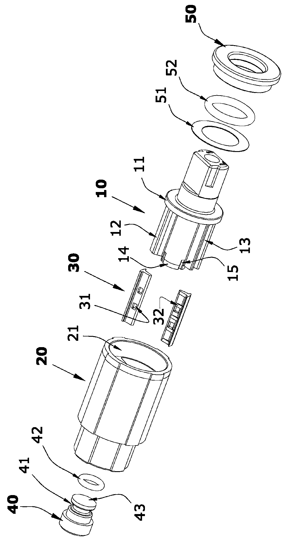
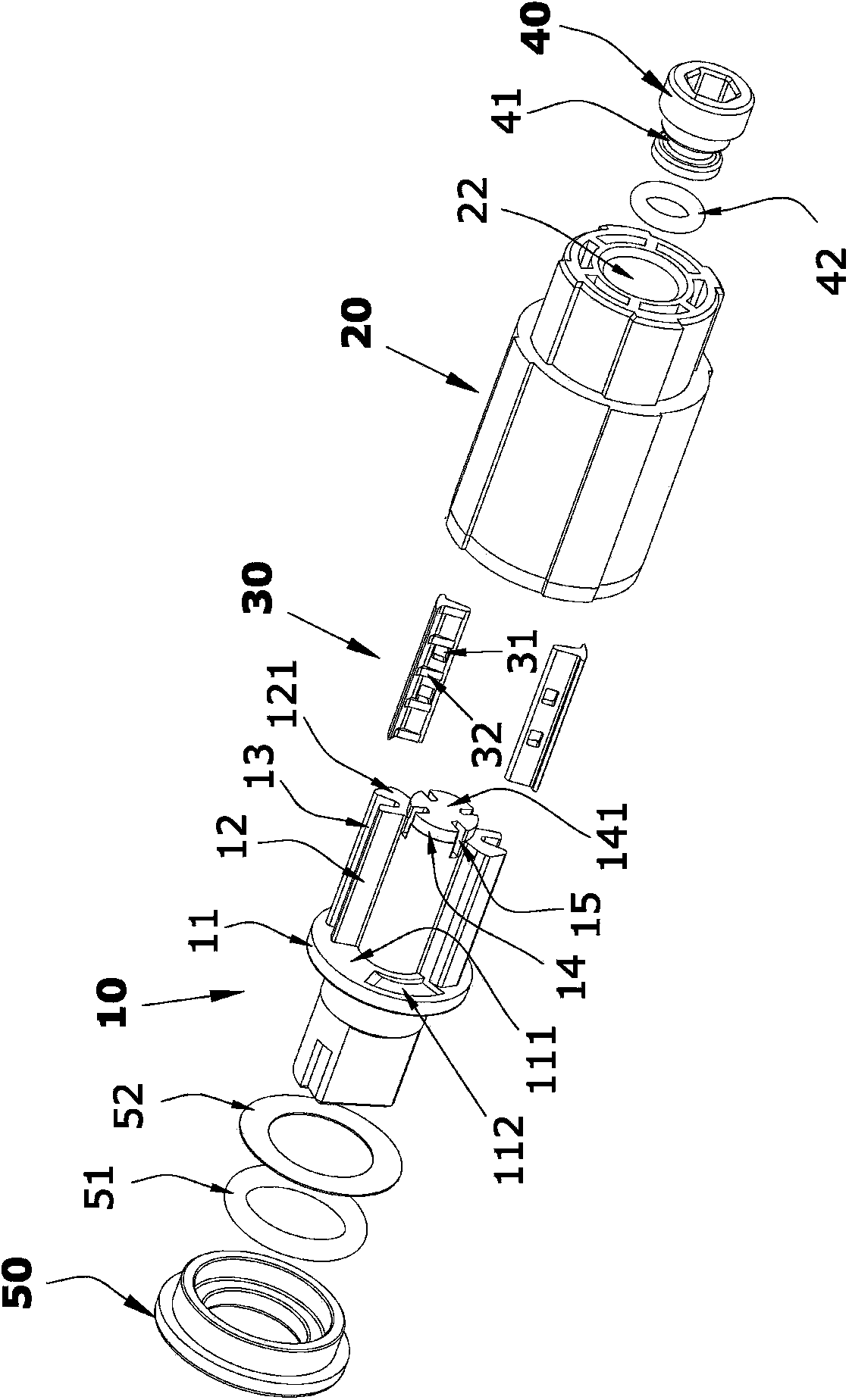
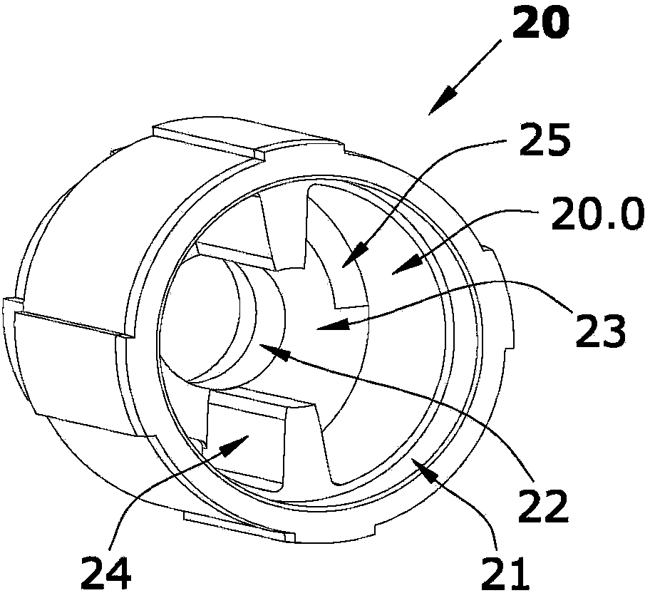
[0033] Such as figure 1 , figure 2 with Figure 9 The rotary buffer with adjustable damping shown is mainly composed of a rotating shaft 10, a shaft sleeve 20, a one-way oil-passing valve plate 30, an adjusting screw 40 and a gland 50; Figure 3 to Figure 9 As shown, the shaft sleeve inner chamber 20.0 of the shaft sleeve 20 of the present invention has an inner cavity opening 21 that can be inserted into the rotating shaft 10 and a shaft through hole 22 for supporting the rotation of the end of the rotating shaft 10. The shaft sleeve inner chamber 20.0 and the shaft through hole 22 forms the bottom surface 23 of the inner cavity, and the center of the two oil-separating ribs 24 is symmetrically arranged on the cavity wall of the inner cavity 20.0 of the shaft sleeve. The opening 21 extends to the inner cavity bottom surface 23 and is fixed, the oil separating rib 24 is flush with the inner cavity openin...

Embodiment 2

[0038] Embodiment 2 (the pressure regulating channel is an L-shaped hole).

[0039] Such as Figure 14 As shown, the difference between this embodiment and Embodiment 1 is that in this embodiment, the pressure regulating channel 15 is an L-shaped hole arranged from the radial surface of the end of the rotating shaft 20 to the shaft end surface 141 of the supporting shaft 14. In this way, the The rotation fit of the support shaft 14 is smoother, and the other structures and working principles of this embodiment are the same as those of the first embodiment.

Embodiment 3

[0040] Embodiment 3 (the pressure regulating channel is an oblique straight hole).

[0041] Such as Figure 15 As shown, the difference between this embodiment and Embodiment 1 is that in this embodiment, the pressure regulating channel 15 is an oblique straight hole arranged from the radial surface at the end of the rotating shaft 20 to the axial end surface 141 of the supporting shaft 14. In this way, The oblique straight-hole pressure-regulating channel 15 is easier to process and ensures smoother rotation of the support shaft 14. The other structures and working principles of this embodiment are the same as those of Embodiment 1.


PUM


Abstract

A damping-adjustable rotary buffer, comprising a shaft sleeve (20) capable of being filled with damping oil, and a rotating shaft (10) hermetically and rotatably mated with the shaft sleeve (20) and capable of disturbing the damping oil flow; the two rotary wing plates (12) of the rotating shaft (10) are respectively sleeved with a one-way oil-flowing valve plate (30), and are slidably mated with the inner cavity wall of the shaft sleeve (20); two oil separating ribs (24) pressing against the rotating shaft (10) and limiting the rotation amplitude of the rotary wing plates (12) are disposed on the inner cavity wall of the shaft sleeve (20); a supporting shaft (14) at the end of the rotating shaft (10) is sleeved in a shaft through hole (22) disposed at the bottom of the shaft sleeve (20); the two sides of each rotary wing plate (12) on the rotating shaft (10) are respectively provided with a pressure adjusting runner (15) communicating a shaft sleeve inner cavity (20.0) with the shaft end surface (141) of the supporting shaft (14); the shaft through hole (22) is screwably connected to an adjustment screw (40); and the end of the adjustment screw (40) is provided with a screw top (43) capable of closely contacting the shaft end surface (141) and plugging the pressure adjusting runner (15). The adjustment screw (40) opens the pressure adjusting runner (15), controls the gap size between the shaft end surface (141) of the supporting shaft (14) and the screw top (43) of the screw (40) so as to adjust the oil flowing speed, changes the hydraulic pressure difference between the two sides of the rotary wing plates (12), and adjusts the damping magnitude of the damping oil to the rotary wing plates (12) so as to control the rotating speed of the rotating shaft (10). The rotary buffer is structurally simple, facilitates damping adjustment, and has a stable and reliable function.

Description

technical field [0001] The invention relates to a hydraulic damping rotary buffer applied to a toilet cover hinge, in particular to a rotary buffer with adjustable damping. Background technique [0002] The existing hydraulic damping rotary buffer is basically composed of a shaft sleeve, a rotating shaft, and a one-way oil paddle. The damping oil in the shaft sleeve is deflected by the shaft. Fast flow in one direction, the damping oil has no hydraulic resistance to the shaft, and the shaft can rotate quickly, but when the shaft rotates in the opposite direction, the oil paddle swings at an angle to close the oil gap so that the damping oil flows slowly, and the damping oil produces hydraulic resistance to act on the shaft , so that the shaft rotates slowly; therefore, adjusting the hydraulic resistance generated by the damping oil in the shaft sleeve (fast oil passing speed, small hydraulic resistance, and small damping) can adjust the speed of the shaft when the damping ro...

Claims


Application Information

Patent Timeline
Patent Type & Authority Patents(China)
IPC IPC(8): A47K13/24
CPCF16F9/14A47K13/12F16F9/145
Inventor 陈国斌
Owner HOTI XIAMEN PLUMBING ING
Why Eureka
Try Eureka