Equipment and method for controlling rotating speed of synchronous magnetic motor

A technology of synchronous reluctance motor and rotation speed, which is applied in the direction of controlling generators, controlling electromechanical brakes, controlling electromechanical transmissions, etc., and can solve problems such as increased costs, inability to achieve speed control, and difficulty in handling Hall sensors.

Inactive Publication Date: 2003-02-12
LG ELECTRONICS INC
View PDF0 Cites 5 Cited by
  • Summary
  • Abstract
  • Description
  • Claims
  • Application Information

AI Technical Summary

Problems solved by technology

[0014] However, conventional equipment that performs the above-mentioned process has torque fluctuations, switching dead time, etc., which are caused by harmonic components included in the detected current frequency fundamental wave, and thus have harmonic components in the induced voltage. wave component
As a result, fluctuations are generated in the estimated rotational speed, so precise speed control cannot be achieved
Also, it is difficult to handle this kind of equipment using the Hall sensor of the encoder and the rotor position detection unit
[0015] Also, the conventional apparatus for controlling the rotational speed of a synchronous reluctance motor has such a problem that the cost increases due to the use of an expensive rotor position detection unit, and although the high-speed control is effective, the low-speed control cannot be smoothly achieved

Method used


Image

  • Equipment and method for controlling rotating speed of synchronous magnetic motor
  • Equipment and method for controlling rotating speed of synchronous magnetic motor
  • Equipment and method for controlling rotating speed of synchronous magnetic motor

Examples


Embodiment Construction

[0025] Description of preferred embodiments

[0026] Preferred embodiments of the invention will now be described in detail, which are illustrated in the accompanying drawings.

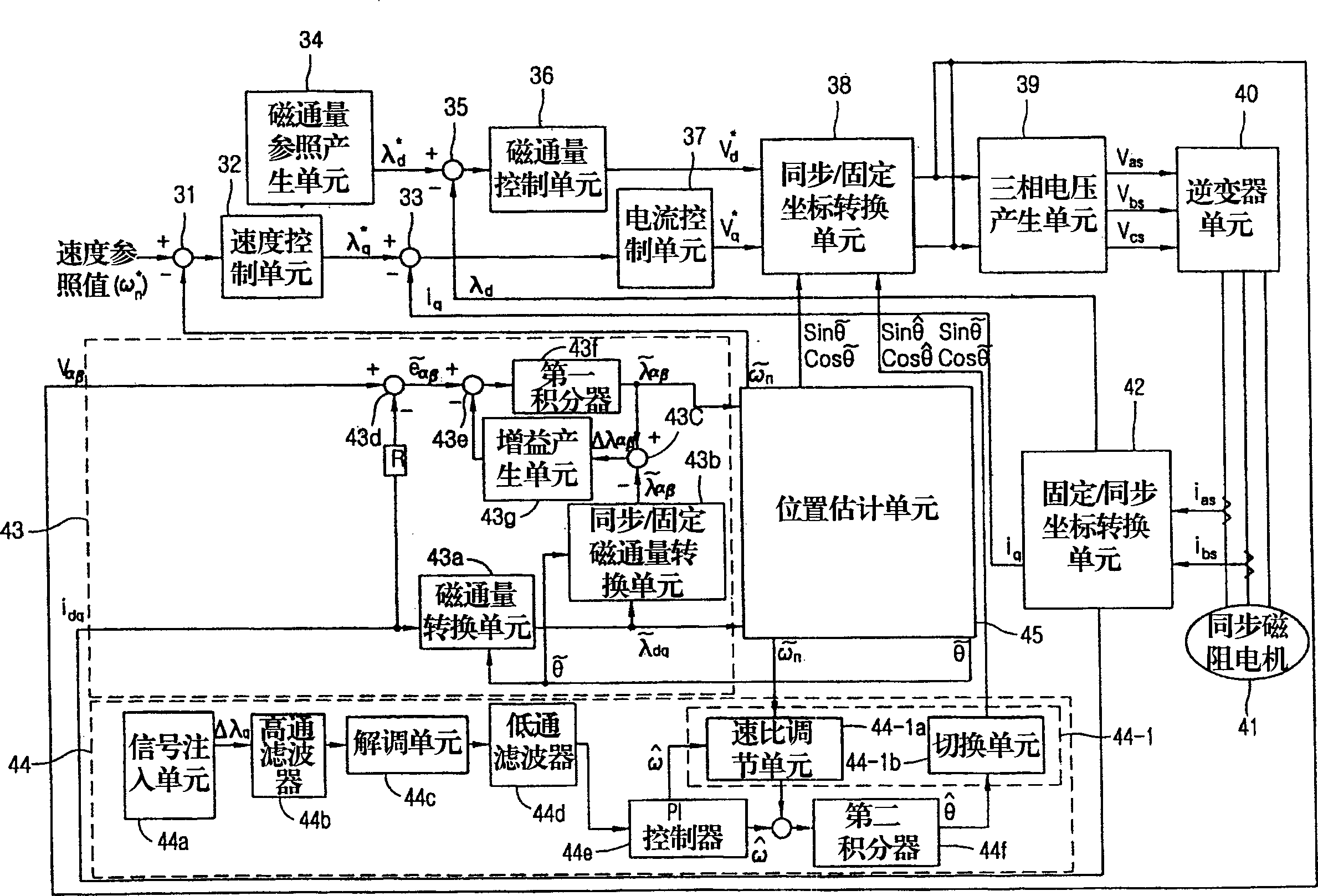
[0027] Below, refer to figure 2 Describe in detail a preferred embodiment of an apparatus for controlling the rotational speed of a synchronous reluctance motor, which does not use hall sensors or encoders to detect the speed and position of the synchronous reluctance motor, but can be controlled separately according to changes in load Low-speed zone and high-speed zone to maintain the accuracy of speed control, in the case where it is difficult to detect the position of the rotor such as in the compressor of refrigerators and air conditioners, it can linearly control the induction variable according to the change of current, thereby accurately controlling the rotation speed of the motor .

[0028] figure 2 It is a structural block diagram of the synchronous reluctance motor of the present inventio...


PUM


Abstract

The invention provides an apparatus for controlling a rotation speed of a synchronous reluctance motor, comprising a first comparator, a speed control unit, a second comparator, a magnetic flux reference generation unit, a third comparator, a magnetic flux control unit, a current control unit, a synchronization / fixed coordinate conversion unit, a three phase voltage generation unit, an inverter unit, a synchronous reluctance motor, a magnetic flux observer, a position estimation unit, a low speed control unit and a transient state stabilization unit. The invention also provides a method for controlling the rotation speed of the synchronous reluctance motor.

Description

technical field [0001] The present invention relates to an apparatus for controlling the rotational speed of a synchronous reluctance motor, and more particularly to such an apparatus for controlling the rotational speed of a synchronous reluctance motor which can pass Detect the input voltage and input current of the synchronous reluctance motor, estimate the speed and flux angle of the motor, and control the rotation speed and torque of the motor. technical background [0002] Generally, for the conventional equipment used to control the rotation speed of synchronous reluctance motors, if instantaneous torque control is performed, the speed or magnetic flux information of the motor must be available, so, for example, tachometers, generators, resolvers, or pulse encoders are required sensors to extract motor speed or flux information. [0003] However, because it is difficult to deal with the above-mentioned sensors, which are sensitive to noise, recently, some foreign com...

Claims


Application Information

Patent Timeline
Patent Type & Authority Applications(China)
IPC IPC(8): H02P27/04H02P21/00H02P21/06H02P21/14H02P21/18H02P21/24H02P21/26H02P21/28H02P23/14H02P23/16H02P23/18H02P27/08
CPCH02P21/0039H02P21/14H02P25/08H02P21/141H02P21/24H02P21/00
Inventor 郑达浩吴在胤李炅勲
Owner LG ELECTRONICS INC
Why Eureka
Try Eureka