Bending device for heat exchanger machining and bending method of heat exchanger

A bending device and heat exchanger technology, applied in the direction of heat exchange equipment, etc., can solve the problems of low processing efficiency, inconvenient to adjust the processing pitch of the spiral heat exchange tube, inconvenient to process the spiral heat exchange tube, etc., and achieve high processing efficiency. Effect

Active Publication Date: 2021-04-30
浙江大升电子开发有限公司
View PDF7 Cites 5 Cited by
  • Summary
  • Abstract
  • Description
  • Claims
  • Application Information

AI Technical Summary

Problems solved by technology

[0004] The purpose of the present invention is to solve the problems in the prior art that the bending machine in the prior art is inconvenient to disassemble and assemble the heat exchange tube during use, so that the processing efficiency is low, and in the bending process, a single Only a certain angle can be bent at a time, which requires multiple pauses, which makes the processing efficiency low, and it is not convenient to adjust the processing pitch of the spiral heat exchange tube, so that it is not easy to process spiral heat exchange tubes of different specifications. Proposed bending device for heat exchanger processing

Method used


Image

  • Bending device for heat exchanger machining and bending method of heat exchanger
  • Bending device for heat exchanger machining and bending method of heat exchanger
  • Bending device for heat exchanger machining and bending method of heat exchanger

Examples


Embodiment Construction

[0032] The following will clearly and completely describe the technical solutions in the embodiments of the present invention with reference to the accompanying drawings in the embodiments of the present invention. Obviously, the described embodiments are only some, not all, embodiments of the present invention.

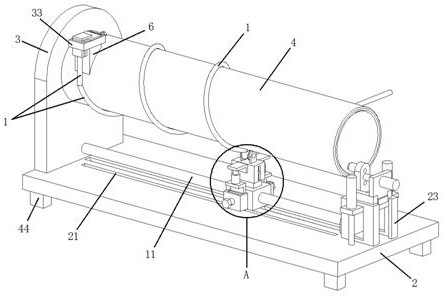
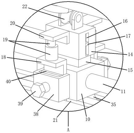
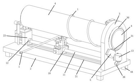
[0033] refer to Figure 1-10 , a bending device for heat exchanger processing, comprising a heat exchange tube 1, a bottom plate 2 is provided on one side of the heat exchange tube 1, a fixing seat 3 is fixed on one side of the bottom plate 2, and a through hole is provided on one side of the fixing seat 3 , the inner side of the through hole is rotatably connected with a rotating cylinder 4, and one side of the fixed seat 3 is fixed with a motor 5, the motor 5 needs to be connected to an external power supply and a switch through a wire, and a first transmission device is provided between the motor 5 and the rotating cylinder 4, The outer side of the rotating cylind...


PUM


Abstract

The invention relates to the technical field of heat exchangers, in particular to a bending device for heat exchanger machining. The bending device for heat exchanger machining comprises a heat exchange tube, a bottom plate is arranged on one side of the heat exchange tube, a fixed seat is fixedly arranged on one side of the bottom plate, a through hole is formed in one side of the fixed seat, a rotating cylinder is rotatably connected to the inner side of the through hole, an electromotor is fixedly arranged on one side of the fixed seat, a first transmission device is arranged between the electromotor and the rotating cylinder, a clamp seat is fixedly arranged on the outer side of the rotating cylinder, a fixed clamping seat is fixedly arranged on one side of the clamp seat, and a detachable clamping seat is arranged on one side of the fixed clamping seat. According to the bending device for heat exchanger machining, the rotating cylinder, the electromotor, the clamp seat, the fixed clamping seat, the detachable clamping seat, a sliding block, a threaded rod, a stepping motor, a lifting box, a connecting block, an ejecting hydraulic cylinder, an L-shaped connecting frame, an ejecting groove wheel and an L-shaped adjusting frame are arranged, the bending device has the functions of automatic bending, automatic screw pitch adjusting, convenient disassembly and assembly, convenient material taking, universality and the like.

Description

technical field [0001] The invention relates to the technical field of heat exchangers, in particular to a bending device for processing heat exchangers. Background technique [0002] A heat exchanger is a device that transfers part of the heat of a hot fluid to a cold fluid, also known as a heat exchanger. Heat exchangers play an important role in chemical, petroleum, power, food and many other industrial productions. Heat exchangers can be used as heaters, coolers, condensers, evaporators and reboilers, etc. Many current heat exchangers need to use bending machines to process straight heat exchange tubes into spiral structures during the manufacturing process. [0003] During the use of the bending machine in the prior art, it is not convenient to disassemble and assemble the heat exchange tube, so that the processing efficiency is low, and in the bending process, only a certain angle can be bent at a time, which requires multiple times Pause makes the processing efficien...

Claims


Application Information

Patent Timeline
Patent Type & Authority Applications(China)
IPC IPC(8): B21D11/06B21D53/06
CPCB21D11/06B21D53/06
Inventor 陈建彬
Owner 浙江大升电子开发有限公司
Why Eureka
Try Eureka