A self-aligning structure for guide rails of medical suspension bridges

A technology for suspension bridges and guide rails is applied in the field of automatic alignment structure, which can solve problems such as increased cost and multiple failure points of parts, and achieves the effect of saving cost, reducing incidence and smooth operation of sliding seat.

Active Publication Date: 2016-12-28
BEIJING AEONMED
View PDF4 Cites 0 Cited by
  • Summary
  • Abstract
  • Description
  • Claims
  • Application Information

AI Technical Summary

Problems solved by technology

The sliding seat can slide on the beam to move the supply column to the required position. When the main wheel of the medical suspension bridge sliding seat slides on the suspension bridge guide rail, because the center of gravity of the heavy objects suspended under the sliding seat and the sliding seat run on the guide rail The paths do not overlap, and the actual running path is bound to deviate from the direction of the suspension bridge guide rail. Therefore, it is necessary to set up an alignment device to perform limit alignment. At present, most of the sliding paths of the main wheels of the medical suspension bridge slides on the market on the suspension bridge guide rail are more A guide wheel or bearing is used to limit the position, so multiple parts may have multiple failure points, and the cost is increased.

Method used


Image

  • A self-aligning structure for guide rails of medical suspension bridges
  • A self-aligning structure for guide rails of medical suspension bridges
  • A self-aligning structure for guide rails of medical suspension bridges

Examples


Embodiment Construction

[0023] The technical solutions of the present invention will be further described below in conjunction with the accompanying drawings and through specific implementation methods.

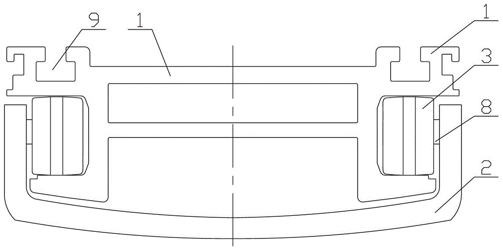
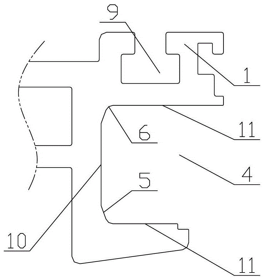
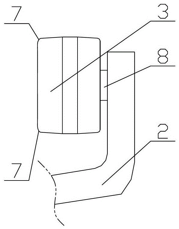
[0024] Such as Figure 1~3 As shown, in this embodiment, a self-aligning structure for a medical suspension bridge guide rail according to the present invention includes a suspension bridge guide rail 1 and a suspension bridge slide seat 2. The cross section of the suspension bridge slide seat 2 is a U-shaped structure, divided into It is two side plates and a bottom plate, the two side plates are arranged in parallel, the distance between the two side plates is greater than the width of the suspension bridge guide rail 1, the bottom plate has an arc-shaped structure with a low center and high ends, and the side plates It is connected with the bottom plate to form an integrated structure. The inner side of the two sides of the suspension bridge slider 2 is provided with a shaft 8, and the main wheel...


PUM


Abstract

The invention discloses an automatic aligning structure for guide rails of a medical suspension bridge. The automatic aligning structure comprises the guide rails of the suspension bridge and a slide seat of the suspension bridge. The section of the slide seat of the suspension bridge is of a U-shaped structure, main wheels of the slide seat are mounted on the inner sides of two side edges of the slide seat of the suspension bridge, slide grooves of the main wheels are formed in two sides of the guide rails of the suspension bridge, the main wheels of the slide seat are matched with the slide grooves of the main wheels, and limiting surfaces for automatically aligning the slide seat of the suspension bridge are arranged at the bottoms of the two slide grooves of the main wheels. The automatic aligning structure has the advantages that the automatic aligning structure is simple, auxiliary components such as guide wheels or bearings can be omitted when the main wheels of the slide seat of the medical suspension bridge roll on the guide rails of the suspension bridge, and an automatic aligning function can be realized by the structures of the guide rails of the suspension bridge; inclined planes and rounded corners are arranged on the guide rails and the main wheels of the slide seat, accordingly, the slide seat can assuredly stably run without jumping in automatic aligning procedures, the cost further can be saved, and the occurrence rate of multiple fault points can be reduced.

Description

technical field [0001] The invention relates to an automatic alignment structure for the guide rail of a medical suspension bridge, which is mainly applied to the problem that the main wheel of the sliding seat of the medical suspension bridge can be automatically aligned when it rolls on the suspension bridge guide rail Background technique [0002] The medical suspension bridge is a combined equipment for medical gas, power supply, communication call and network terminal installed on the ceiling. It can carry the medical equipment needed by the patient, provide a good nursing space in the operating room, and improve the convenience, comfort and convenience of the working environment. Safety and hygienic conditions, its function is simple and practical, easy to operate, it is an ideal equipment for operating room, ICU, emergency room. [0003] In-service suspension bridge products often include one or more slides to attach the supply column to the suspension bridge beam. T...

Claims


Application Information

Patent Timeline
Patent Type & Authority Patents(China)
IPC IPC(8): A61G12/00A61B90/00
Inventor 刘丽君
Owner BEIJING AEONMED
Why Eureka
Try Eureka