Novel impeller feeder

An impeller feeder, a new type of technology, applied in conveyors, rotary conveyors, transportation and packaging, etc., can solve the problems of short blade maintenance cycle, large useless power consumption of the feeder, impeller can not rotate, etc. The effect of equipment maintenance, improving control accuracy, and preventing material jams

Inactive Publication Date: 2014-07-02
CHINA UNIV OF MINING & TECH
View PDF9 Cites 18 Cited by
  • Summary
  • Abstract
  • Description
  • Claims
  • Application Information

AI Technical Summary

Problems solved by technology

[0004] In actual production, under different application conditions, the impeller feeder has some shortcomings, and some problems will occur, which will affect the normal production in severe cases
For example, when the feed material contains a large amount of materials with large hardness and particle size, the problem of material jamming between the blade and the edge of the material often occurs. When it is more serious, the forward and reverse rotation of the impeller is blocked, and the impeller cannot rotate. The feeder cannot run, and the amount of material in the silo is relatively large, so maintenance will be very difficult
In addition, due to relying on the gap between the blade and the side wall to seal the material, severe wear and leakage will occur during operation. When the material supplied by the equipment is a abrasive material, the maintenance cycle of the blade will be shorter, which will Seriously affect the normal production operation, and there will always be materials stuck between the blade and the shell during the conveying process, the material is seriously broken, the useless power consumption of the feeder is large during operation, and the electric energy is seriously wasted

Method used


Image

  • Novel impeller feeder
  • Novel impeller feeder

Examples


Embodiment Construction

[0019] The present invention will be further explained below in conjunction with the accompanying drawings.

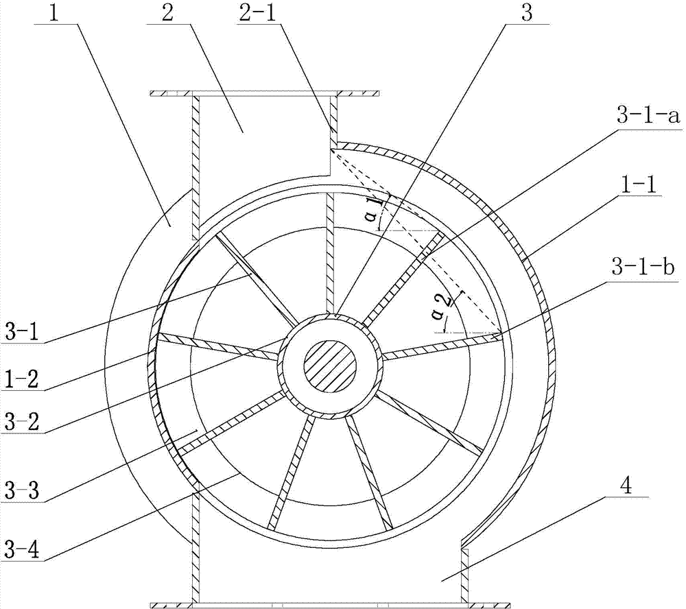
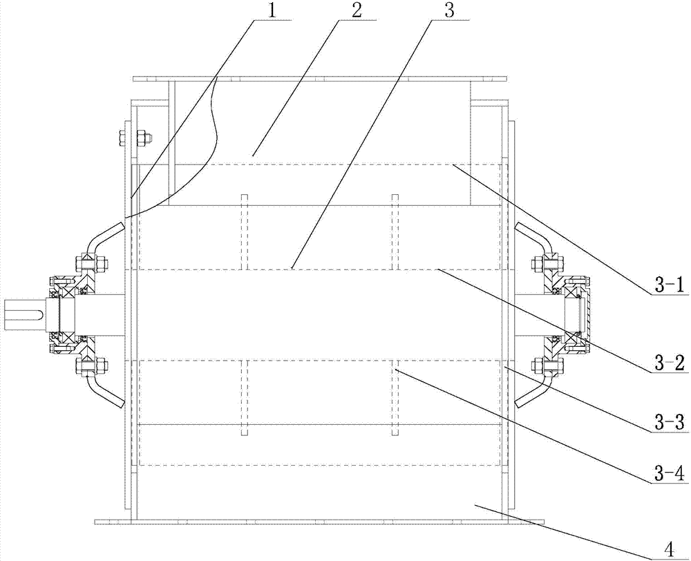
[0020] like figure 1 and 2 As shown, the novel impeller feeder of the present invention includes a casing 1, a material inlet 2, an impeller 3 and a material outlet 4. The casing 1 is a load-bearing main structure and also a slideway for material delivery. There is a material inlet 2 on the upper part of the casing 1, and the material inlet 2 can be installed vertically or inclined. In the case of an inclined arrangement, most of the height pressure of the material will be borne by the feeding connection chute. The bottom of the casing 1 is provided with a discharge port 4, because there is no use of multiple blades to close the material, so the discharge port 4 is arranged below the discharge channel. The impeller 3 is arranged inside the casing 1, and the impeller 3 is the basis for promoting material movement and transmitting power, and it includes a blade 3-1, a...


PUM


Abstract

The invention discloses a novel impeller feeder. The novel impeller feeder comprises a case. A feeding port and a discharge port are formed in the upper portion of the case and the lower portion of the case respectively. An impeller is arranged in the case and comprises a wheel groove bottom with which a rotating shaft is sleeved. A plurality of blades are arranged on the periphery of the wheel groove bottom at intervals in the peripheral direction. N upwardly-inclined blades are arranged in the area, corresponding to the conveying-side inner wall of the case, of the impeller, wherein N is larger than or equal to 2, and the included angle formed between the horizontal plane and the connecting line of the radial edge of at least one of the N blades and the lower end of the conveying-side edge wall of the feeding port is smaller than the angle of repose of materials. The gap between the conveying-side inner wall of the case is 2.5 times larger than the maximum diameter of the materials. The novel impeller feeder is compact in structure, serious abrasion is avoided on the premise that the requirement for full-width feeding is met, blockage caused by the materials can be prevented, control precision can be improved, and the maintenance workload and power consumption of the novel impeller feeder are substantially reduced.

Description

technical field [0001] The invention relates to a conveying machine, which is especially suitable for the quantitative feeding of dry granular materials and the production process that cannot be fed intermittently for a long time. Background technique [0002] Quantitative feeding equipment is often used in the engineering field. The common quantitative feeding equipment mainly includes: vibrating feeder, belt feeder, scraper feeder, screw feeder, impeller feeder machine etc. The foundation required for the installation of the vibrating feeder is firm and it is difficult to realize the linear fine adjustment of the feeding amount; the belt feeder is difficult to be fully sealed due to the adjustment requirements, and the dust-proof effect is poor; the scraper type feeder It belongs to pulsating feeding, and the feeding is not uniform and stable; although the screw feeder can feed stably, it is a point feeding, and the feeding width is narrow and not uniform enough in the en...

Claims


Application Information

Patent Timeline
Patent Type & Authority Applications(China)
IPC IPC(8): B65G29/00
Inventor 赵跃民骆振福梁春成江海深段晨龙周恩会钟莉平
Owner CHINA UNIV OF MINING & TECH
Why Eureka
Try Eureka