Hydraulic support working posture determining method based on space coordinate converting

A technology of hydraulic support and determination method, which is applied in the directions of pillar/support, earth-moving drilling, mining equipment, etc., can solve the problems such as the inability to obtain the determined position and angle of each component of the support, the waste of system resources, and the inability to determine the working attitude of the hydraulic support.

Active Publication Date: 2014-07-02
CHINA UNIV OF MINING & TECH +1
View PDF4 Cites 29 Cited by
  • Summary
  • Abstract
  • Description
  • Claims
  • Application Information

AI Technical Summary

Problems solved by technology

[0003] However, due to the continuous shifting and complex and changeable working environment of the coal mining face, the hydraulic support is subjected to huge impact loads from coal, rocks, etc., as well as pollution from coal dust, water mist, etc. The length of the drive cylinder of the support cannot be accurately measured, which leads to the uncertainty of the current accurate working posture of the hydraulic support, which affects the accuracy of remote monitoring
[0004] At present, among the existing support attitude measurement methods and height measurement methods, the Chinese patent with the publication number CN101358532A discloses a hydraulic support with an inclination sensor to measure the attitude of the support, but the base plate is not equipped with an inclination sensor, so it cannot be determined The working posture of the stand when it is tilted cannot be applied to the remote monitoring of the stand
The Chinese patent with the publication number CN102392664A discloses a method for measuring the height of the hydraulic support. Although the method takes into account the angle change of the bottom plate, it uses four inclination sensors, which wastes system resources. In addition, this method cannot obtain Determine the position and angle of each component of the bracket in space

Method used


Image

  • Hydraulic support working posture determining method based on space coordinate converting
  • Hydraulic support working posture determining method based on space coordinate converting
  • Hydraulic support working posture determining method based on space coordinate converting

Examples


Embodiment Construction

[0024] The present invention will be further described below in conjunction with the accompanying drawings and specific embodiments.

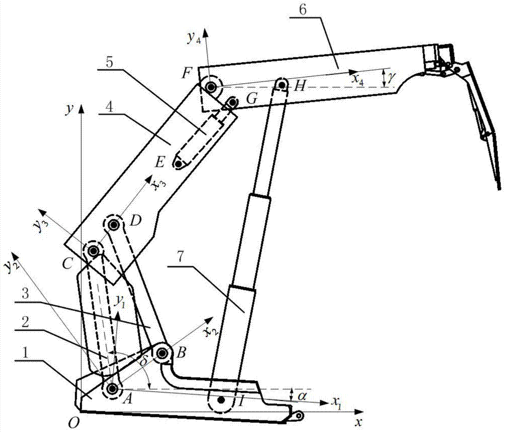
[0025] Such as figure 1 As shown, a method for determining the working posture of a hydraulic support based on spatial coordinate transformation includes the following steps:

[0026] (1) Through the sensors installed on the top beam 6, the first connecting rod 2, the second connecting rod 3 and the base 1, the inclination angle of the plane where the coordinate system of each component of the hydraulic support is located relative to the reference coordinate system can be measured in real time, that is, Obtain base compensation inclination α, connecting rod inclination δ and top beam inclination γ; the sensor signal output port is connected to the control device of the hydraulic support, and the control device obtains the sensor signal and corresponds to the model established in the control device;

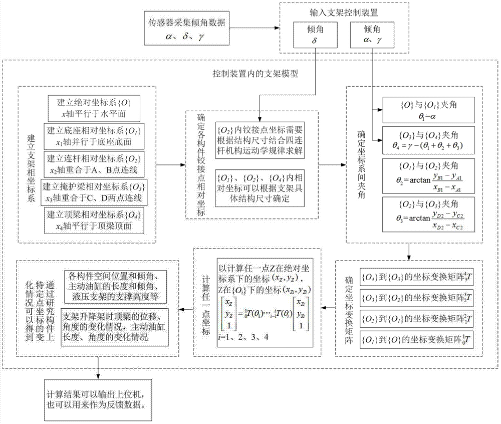
[0027] (2) Establish the mathematical mode...


PUM


Abstract

The invention discloses a hydraulic support working posture determining method based on space coordinate converting. The working posture of a four-bar linkage hydraulic support is obtained by measuring the dip angle value of changing of a support member in real time. The inclination angle, relative to a reference coordinate system, of a base of the hydraulic support, the inclination angle, relative to the reference coordinate system, of a connecting rod of the hydraulic support and the inclination angle, relative to the reference coordinate system, of a top beam of the hydraulic support are measured in real time, and the positions and angles of the current members and the length of a driving oil cylinder are worked out by establishing the reference coordinate system and a relative coordinate system according to the three angle values and the geometric dimensioning of the support. The hydraulic support working posture determining method is accurate in measurement, the measuring method is simple, and the hydraulic support working posture determining method can be transplanted to a controller or upper computer software conveniently.

Description

technical field [0001] The invention relates to a method for determining the working posture of a hydraulic support, in particular to a method for determining the working posture of a hydraulic support based on space coordinate transformation. Background technique [0002] Many coal mines in my country have established fully-mechanized mining automation production areas, and equipped with fully-mechanized mining equipment remote monitoring function. The real-time, reliable and intuitive remote monitoring of the hydraulic support can not only grasp the accurate operation status of the hydraulic support in time, but also predict the support quality of the hydraulic support, so as to predict its failure, and adjust the operating parameters of the support according to the monitoring results . It is particularly important to ensure that the virtual hydraulic support model is consistent with the actual support movement. [0003] However, due to the continuous shifting and comple...

Claims


Application Information

Patent Timeline
Patent Type & Authority Applications(China)
IPC IPC(8): E21D15/51
Inventor 闫海峰王秋实王忠宾谭超周晓谋姚新港刘新华刘继东
Owner CHINA UNIV OF MINING & TECH
Why Eureka
Try Eureka