Power distribution fault studying and judging method based on multisystem collaboration

A multi-system, fault technology, applied in the direction of the fault location, etc.

Active Publication Date: 2014-07-02
STATE GRID TIANJIN ELECTRIC POWER +1
5 Cites 46 Cited by

AI-Extracted Technical Summary

Problems solved by technology

However, due to the fact that there is still a lot of room for improvement in the level of informatization and automation construct...

Abstract

The invention relates to a power distribution fault studying and judging method based on multisystem collaboration. The method comprises the following steps: a power distribution transformer object is positioned; whether the scheduled power outage is performed is judged; the known fault power outage is judged; a power outage range is defined by adopting an asynchronous interrogation mode; and a low-voltage line fault is judged. According to the studying and judging method, more comprehensive analysis of the operation state of a power distribution network is facilitated, detailed basis is provided for fault processing and standardized first-aid repair work of a power supply system, and accurate power supply device positioning and fault range defining functions are provided for low-voltage user repair reporting processing. Meanwhile, the acquired reading inquiring function of real-time electricity-using readings of intelligent meter users and the attributed power distribution transformers can be basically realized by the studying and judging method so that powerful auxiliary means are provided for real-time and accurate definition of repair reporting accident range for repair reporting users.

Application Domain

Fault location

Technology Topic

First aidElectricity +8

Image

  • Power distribution fault studying and judging method based on multisystem collaboration
  • Power distribution fault studying and judging method based on multisystem collaboration
  • Power distribution fault studying and judging method based on multisystem collaboration

Examples

  • Experimental program(1)

Example Embodiment

[0034] The following describes the embodiments of the present invention in further detail with reference to the accompanying drawings: it should be emphasized that the embodiments of the present invention are illustrative rather than restrictive, and the protection scope of the present invention cannot be limited by this.
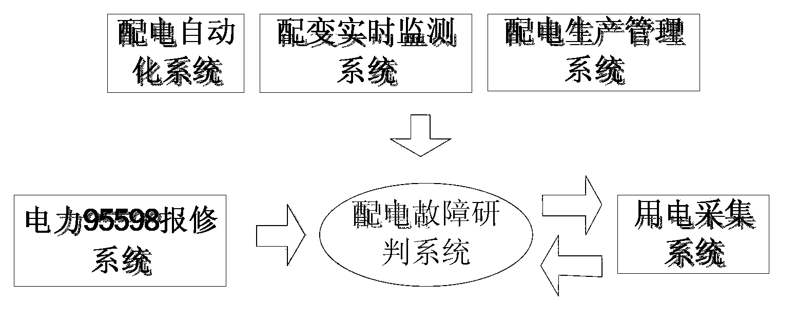
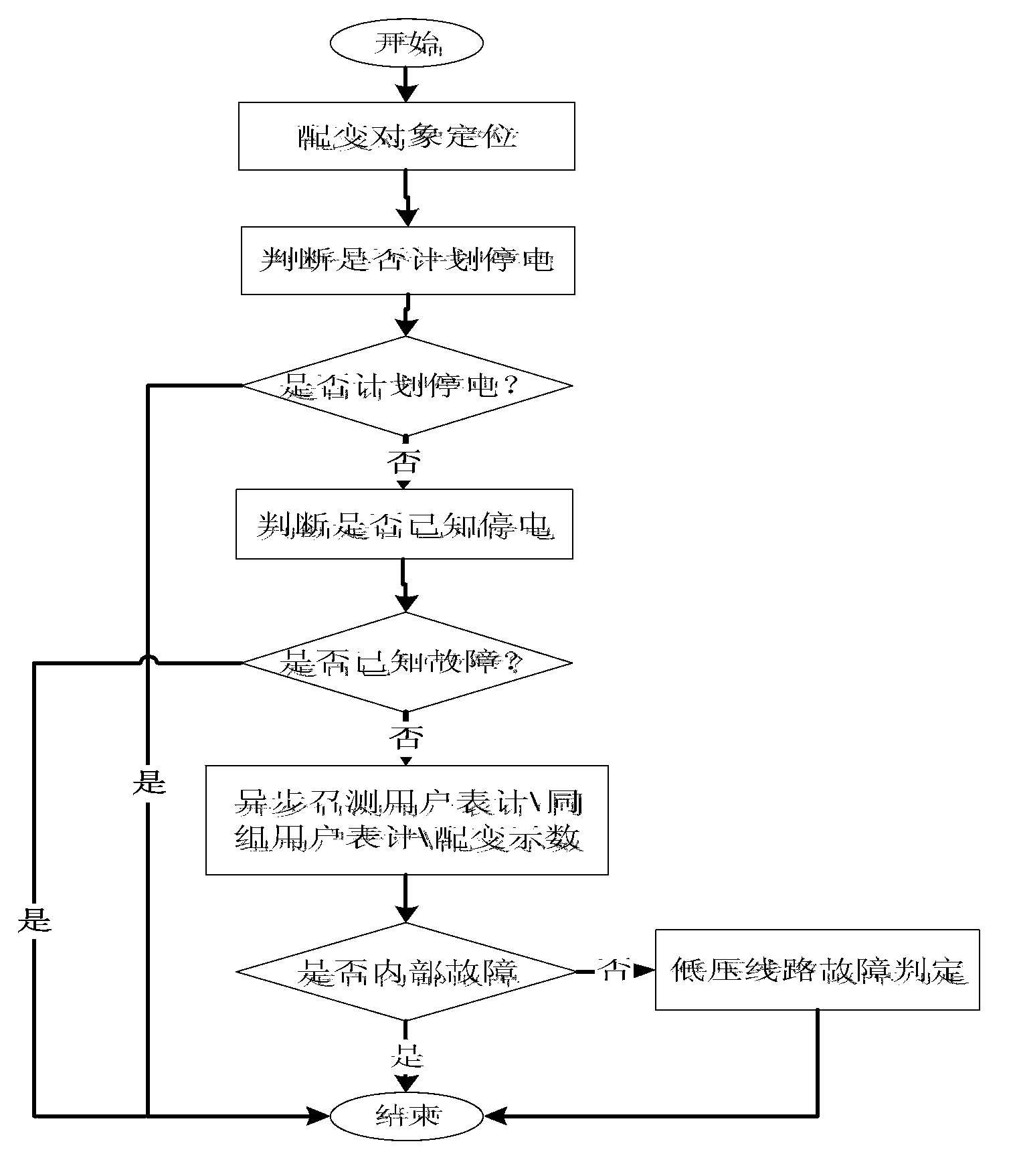
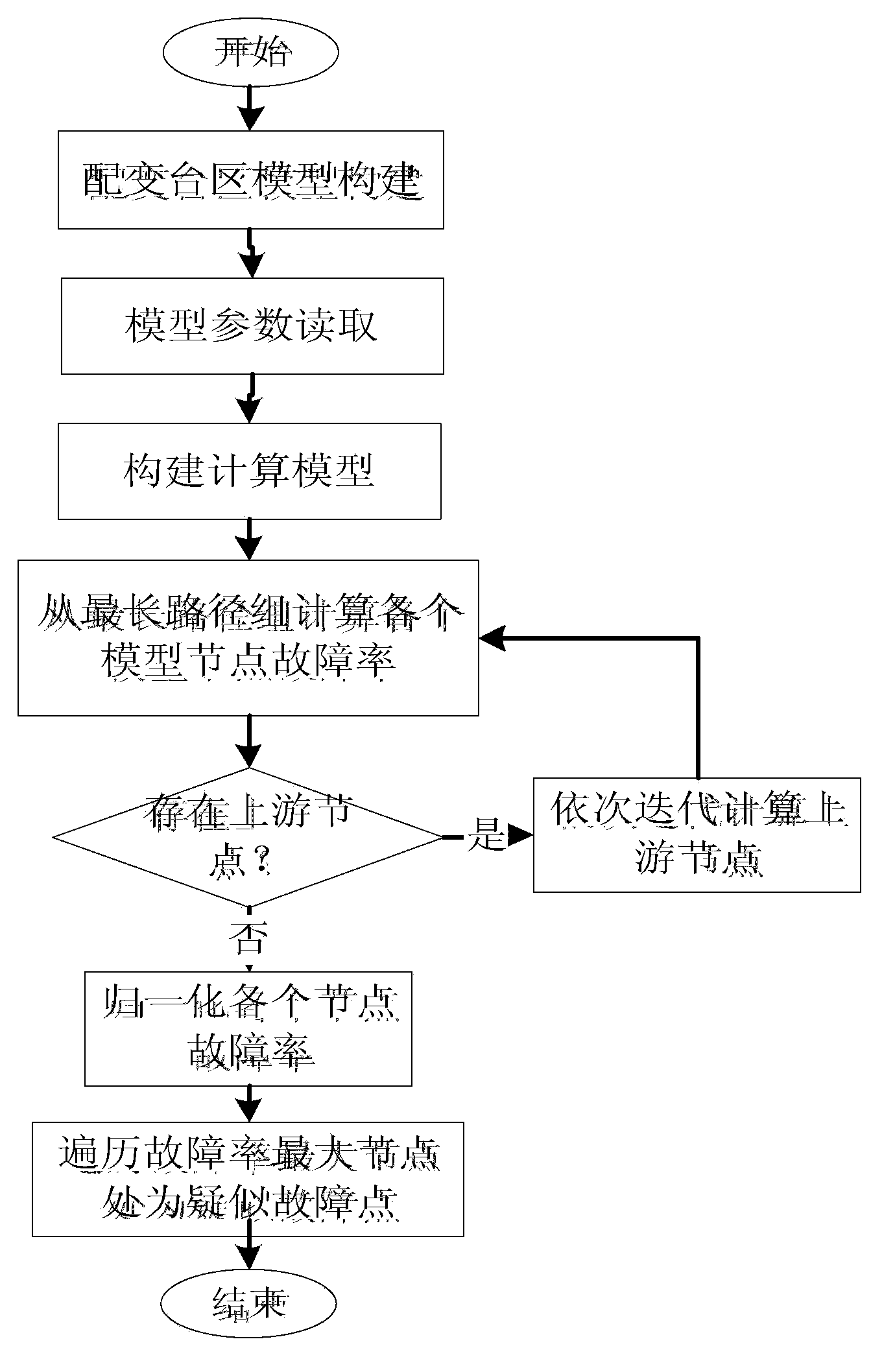
[0035] A power distribution fault research and judgment method based on multi-system cooperation, such as figure 1 As shown, the research and judgment method is based on the established power distribution automation system (DMS), comprehensive power acquisition system, distribution transformer real-time monitoring system, power distribution production management system and power 95598 repair report based on the 95598 fault The repair request is realized by the initial trigger condition. The innovation of the present invention is to realize the automatic research and judgment of the fault of the medium voltage equipment, and realize the automatic research and judgment of the fault of the low voltage equipment, such as figure 2 As shown, the working steps of the inventive method are as follows:
[0036] ⑴Distribution variable object positioning:
[0037] Based on the repair information of the resident customer 95598, match the user meter box according to the repair account number and address, and then trace back to the power supply transformer object based on the topology calculation to realize the association of the resident user to the power supply transformer.
[0038] ⑵ Determine whether there is a planned power outage:
[0039] After the power outage plan is maintained by the distribution production management system, the fault research and judgment system queries the current outage plan that is currently being executed, and judges whether the distribution transformer object currently located for repair is in the outage plan based on the outage range, that is, the set of distribution transformers. If it is within the impact of the power outage plan, the judgment will end and the judgment result will be returned.
[0040] ⑶ Determine whether the power failure is known:
[0041] ①in figure 1 The distribution automation system and the distribution transformer online monitoring system can capture real-time fault information in the power grid in real time, and process the captured real-time fault information, including distribution transformers, feeder sections, and switches affected by the fault according to the feeder object , The load equipment is grouped to form a fault event, and the set of distribution transformers affected by each fault event and the set of user meter boxes affected by each fault event are calculated;
[0042] ② Inquire whether the distribution transformer object currently located for repair is included in the captured known fault information. If it is within the influence range of the fault event, the research and judgment will end and the research and judgment result will be returned.
[0043] ⑷Using asynchronous call-to-test method to define the scope of power failure:
[0044] ①Asynchronously call user meters, the same group (same meter box) user meters, and distribution variable indications; through the research and judgment system in real time figure 1 The power consumption collection system in the system communicates, calls the current user meter for repair, the meter of the user in the same group, and the indicator of the distribution variable, determines the current charging status, and assists in defining the fault range;
[0045] ② If users in the same group (same meter box) are powered on, it can be judged that the current user is a single-house internal fault, the judgment is over, and the judgment result is returned.
[0046] ⑸ Low-voltage line fault judgment:
[0047] If the current user meter or the user meter of the same group loses power and it is judged to be a low-voltage line fault, then the specific low-voltage line fault point is judged based on the current distribution of all user repair faults under the distribution transformer, such as image 3 As shown, the specific steps of the judgment process are as follows:
[0048] ① Construction of the distribution transformer station area model, with the distribution network transformer as the root node, sequentially search for the downstream distribution network low-voltage switch and low-voltage user meter box objects to construct a low-voltage network tree;
[0049] ②Read the model parameters of the distribution transformer station area. Before the fault point research and judgment, the research and judgment system maintains the failure probability model of each equipment type (distribution transformer, low-voltage branch switch, low-voltage meter box), which is used to characterize the failure rate of each equipment type The calculation relationship with the downstream fault report information, after the construction of the distribution transformer zone model is completed, the model parameters of each node are read for calculation in the later study and judgment;
[0050] ③Construct a calculation model. Based on the above distribution transformer station area model and its parameter configuration, construct a unified failure rate calculation method for each node under the distribution transformer station area including distribution transformers, low-voltage branch switches and low-voltage meter boxes, including two parts, details as follows:
[0051] a. Under a node CB, there are M downstream low-voltage meter boxes. If there are M low-voltage meter boxes with fault repair objects, the numbers are n1, n2,..., nM, then the failure probability of this node is:
[0052] CB=C1*c1+C2*c2.
[0053] Among them: c1+c2=1. CB is the possibility of node comprehensive failure;
[0054] C1=Σ((ni-Si*ɑi)> 0? (ni-Si*ɑi):0)*L/Si, where ni is the number of repairs for low-voltage meter box i, Si is the total number of low-voltage users of low-voltage meter box i, ɑi is the internal failure threshold of low-voltage users, L Is the model parameter;
[0055] C2=Σni*(A (m-1) -1) K/Si, where ni is the number of failure reports for low-voltage meter box i, Si is the total number of low-voltage users of low-voltage meter box i, and A and K are model parameters;
[0056] b Correction process: Under a node CB, if there is N(N> 0) A direct downstream low-voltage meter box object, and no fault report is generated, the correction is as follows:
[0057] CB=H*B (1-N) *CB
[0058] Among them: B is the correction index, H is the correction ratio;
[0059] After the failure report arrives, calculate according to the constructed calculation model;
[0060] ④Calculate the failure rate of each model node from the longest path group, and calculate the failure rate of the node from the node furthest from the distribution transformer based on the constructed research and judgment model, and according to the fault report information;
[0061] ⑤ Iteratively calculate the upstream nodes in turn. After each current node (low-voltage branch switch or low-voltage meter box) failure rate is calculated, continue to iteratively calculate the failure rate of the upstream node until the failure rate of all nodes is calculated;
[0062] ⑥ Normalize the failure rate of each node. After calculating the failure rate of all nodes, for the convenience of comparison, it is necessary to normalize the failure rate of all nodes in the low-voltage model to ensure that the failure rate of each node is expressed as a percentage .
[0063] ⑹Judgement of failure point:
[0064] According to each node object, traverse the upstream node object of the node in turn, compare the calculated failure rate, and the node with the highest failure rate can be judged as the failure point.

PUM

no PUM

Description & Claims & Application Information

We can also present the details of the Description, Claims and Application information to help users get a comprehensive understanding of the technical details of the patent, such as background art, summary of invention, brief description of drawings, description of embodiments, and other original content. On the other hand, users can also determine the specific scope of protection of the technology through the list of claims; as well as understand the changes in the life cycle of the technology with the presentation of the patent timeline. Login to view more.
Why Eureka
Try Eureka