Passive wireless current transformer

A current transformer, passive wireless technology, applied in the direction of inductors, instruments, circuits, etc., can solve the problems of high construction cost, limited installation position of current transformer, excessive value of cables, etc., and achieve low cost, convenient and fast transmission Effect

Inactive Publication Date: 2014-07-02
SUZHOU IND PRAK NEW HONGBO COMM TECH
View PDF3 Cites 6 Cited by
  • Summary
  • Abstract
  • Description
  • Claims
  • Application Information

AI Technical Summary

Problems solved by technology

[0002] Traditional current transformers are secondary mutual inductance and wired transmission. In this way, during the construction and installation process, the length of the wiring during construction will be different due to the distance between the measurement point and the detection meter, and the sampling accuracy will decrease due to the loss of the line. The data is inaccurate and the deviation is large
Because it is wired tra

Method used


Image

  • Passive wireless current transformer

Examples


Embodiment Construction

[0011] In order to make the objectives, technical solutions and advantages of the present invention clearer, the present invention will be described in detail below with reference to the accompanying drawings and specific embodiments.

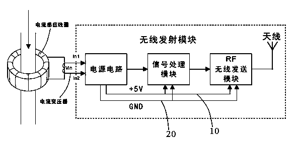
[0012] Such as figure 1 As shown, the passive wireless current transformer of the present invention includes a current induction coil, a current transformer connected to the current induction coil, and a wireless transmitting module connected to the current transformer. The wireless transmitting module includes a power circuit connected to the current transformer, a signal processing module connected to the power circuit, and an RF wireless transmitting module connected to the signal processing module.

[0013] The power circuit is further divided into two branches to the outside, and the two branches include a first branch 10 for providing +5V power and a second branch 20 for grounding. The first branch 10 is respectively connected to the signal p...


PUM


Abstract

The invention provides a passive wireless current transformer. The passive wireless current transformer comprises a current induction coil, a current transformer body connected with the current induction coil, and a wireless transmitting module connected with the current transformer body, wherein the wireless transmitting module comprises a power circuit connected with the current transformer body, a signal processing module connected with the power circuit, and an RF wireless sending module connected with the signal processing module.

Description

Technical field [0001] The invention relates to a current transformer, in particular to a passive wireless current transformer. Background technique [0002] Traditional current transformers are two-time mutual inductance and wired transmission. During the construction and installation process, the distance between the measuring point and the detection meter will cause the length of the wiring in the construction to be different, and the sampling accuracy will decrease due to the loss of the line. The data is inaccurate and the deviation is large. Because it is wired transmission, on-site construction is very difficult and the construction cost is also very high. Sometimes the value of the cable exceeds the current transformer itself due to the distance, which invisibly increases the cost. Because it is a later stage of construction, it is often subject to the requirements of wiring, which results in the installation position of the current transformer is greatly restricted, whi...

Claims


Application Information

Patent Timeline
IPC IPC(8): H01F38/30H01F38/32H01F38/14G01R15/00H02J17/00H02J50/10
Inventor 严明
Owner SUZHOU IND PRAK NEW HONGBO COMM TECH
Why Eureka
Try Eureka