The method of judging the hinges with ring marks produced by parallel machine tools

A wheel pattern and machine tool technology, which is applied in metal processing machinery parts, metal processing equipment, measuring/indicating equipment, etc., can solve the problems of shape error, affecting the accuracy of workpieces processed by parallel machine tools, and achieve the effect of improving processing accuracy.

Inactive Publication Date: 2017-06-06
HUAIYIN INSTITUTE OF TECHNOLOGY
View PDF4 Cites 0 Cited by
  • Summary
  • Abstract
  • Description
  • Claims
  • Application Information

AI Technical Summary

Problems solved by technology

[0005] The wheel pattern on the surface of the workpiece causes the disadvantages of the workpiece: the wheel pattern on the surface of the workpiece affects the surface shape of the wheel pattern due to the surface protrusion, resulting in shape errors and affecting the accuracy of the parallel machine tool to process the workpiece, especially the obvious wheel pattern

Method used


Image

  • The method of judging the hinges with ring marks produced by parallel machine tools
  • The method of judging the hinges with ring marks produced by parallel machine tools
  • The method of judging the hinges with ring marks produced by parallel machine tools

Examples


Embodiment 1

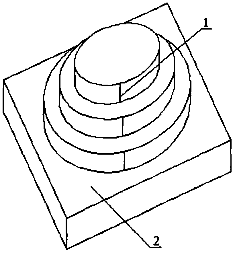
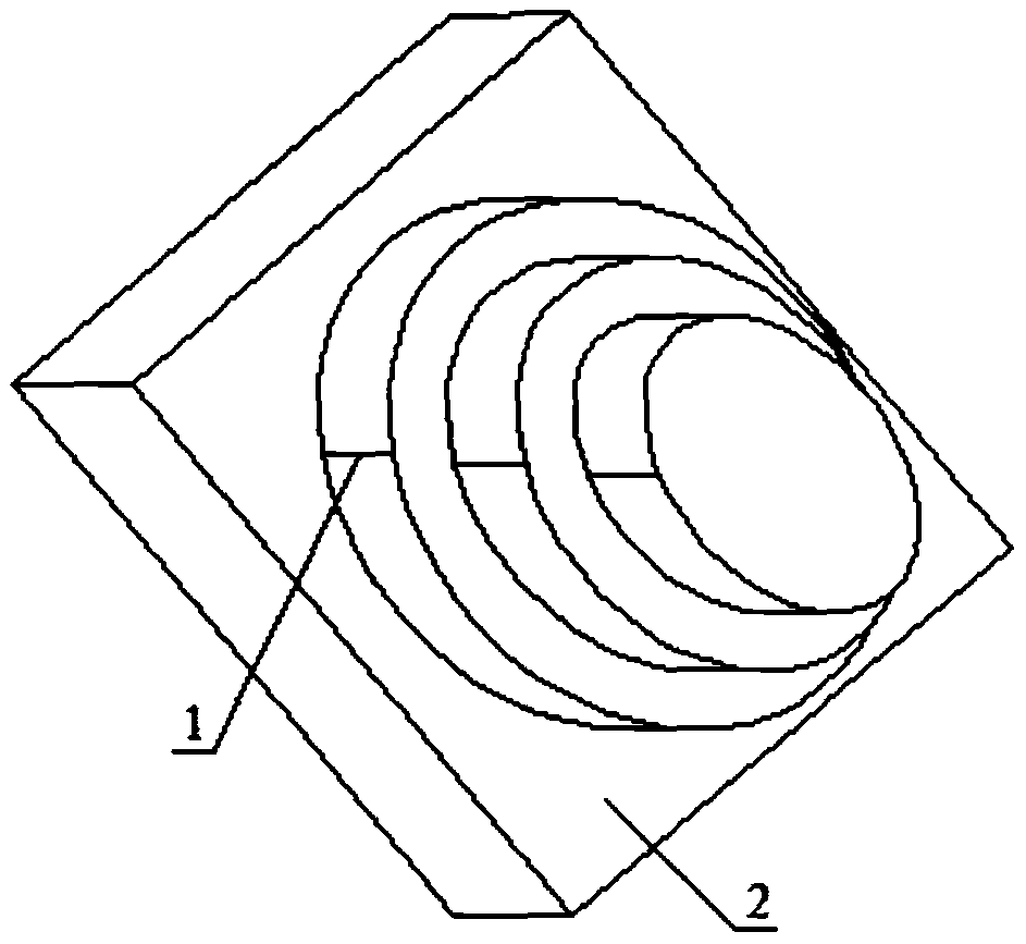
[0037] Embodiment 1: with image 3 Taking the cylindrical workpiece 2 with a diameter of φ100mm processed by the parallel machine tool 3 as an example, the hinge of the wheel pattern 1 produced by the parallel machine tool 3 is judged.

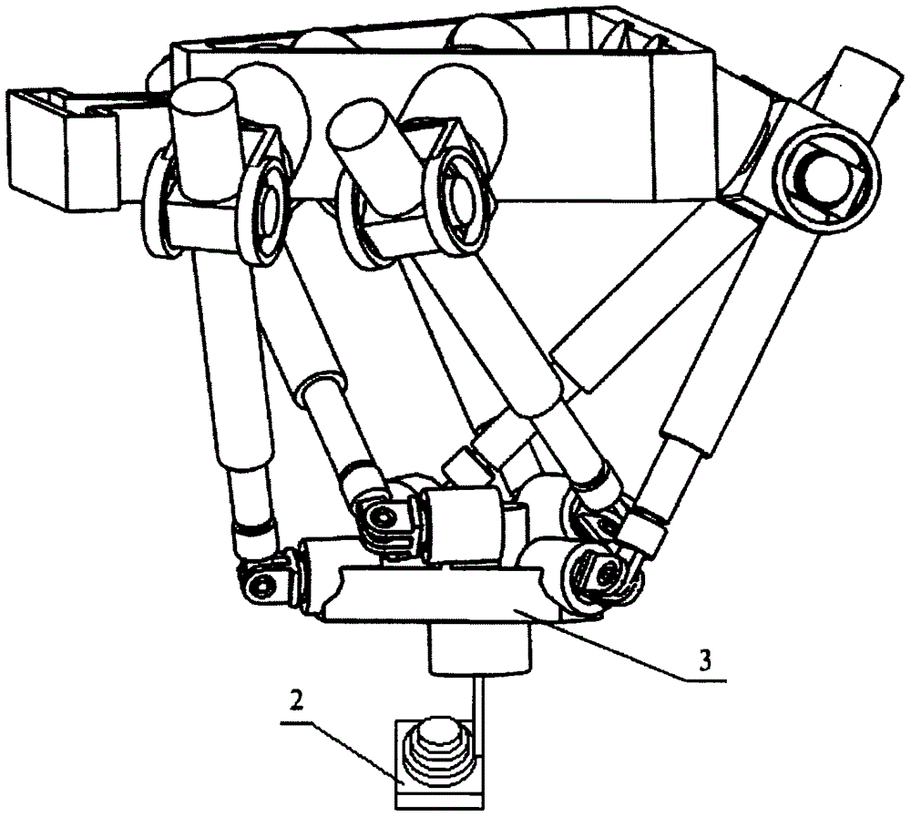
[0038] Parallel machines such as Figure 4 As shown, the structure diagram of the parallel machine tool is as follows Figure 5 As shown, the fixed platform 7 and the spline sleeve 8 pass through the universal joint B i connection, the moving platform 14 and the spline shaft 9 pass through the universal joint b i Connection, the spline sleeve 8 and the spline shaft 9 are spline connection, one end of the spline shaft 9 is connected with the servo motor 4, the electric spindle 13 is installed at the center of the moving platform 14, and the tool 12 is installed at the lower end of the electric spindle 13; The key sleeve 8 and the spline shaft 9 form a connecting rod, and the universal hinge B i with universal hinge b i The spline sleeve 8 ...

Embodiment 2

[0048] Embodiment 2: with image 3 Taking the cylindrical workpiece 2 with a diameter of φ80mm processed by the parallel machine tool 3 as an example, the hinge of the wheel pattern 1 generated by the parallel machine tool 3 is judged.

[0049] The step of judging the hinge that the parallel machine tool 3 produces the wheel pattern 1 is the same as that in embodiment 1, measured with a coordinate measuring machine 15 Figure 1~2 The two wheel patterns 1 on the surface of the cylindrical workpiece 2 with a diameter of φ80mm shown are respectively at the corners of 18.6° and 36.6° at the center of the moving platform 14 around the axis of the workpiece 2, calculated according to the structure of the parallel machine tool 3 and the movement of the connecting rod See Table 2 for the rotation angle of the center of the moving platform 14 around the axis of the workpiece 2 when the connecting rod reverses around the moving and fixed axes of the universal joint, and the connecting ro...

Embodiment 3

[0052] Embodiment 3: with image 3 Taking the cylindrical workpiece 2 with a diameter of φ60mm processed by the parallel machine tool 3 as an example, the hinge of the wheel pattern 1 generated by the parallel machine tool 3 is judged.

[0053] The step of discriminating the hinge that the parallel machine tool produces the wheel pattern is the same as that in embodiment 1, measured with a coordinate measuring machine 15 Figure 1~2 The two wheel patterns 1 on the surface of the cylindrical workpiece 2 with a diameter of φ60 mm shown are respectively at the corners of 19.1° and 36.3° at the center of the moving platform 14 around the axis of the workpiece 2, calculated according to the structure of the parallel machine tool 3 and the movement of the connecting rod Connecting rod B 3 b 3 Universal hinge b on the revolving platform 14 3 When the moving shaft of the moving platform is reversed relative to the moving platform 14, the rotation angles of the center of the moving p...


PUM


Abstract

The invention discloses a method for judging a hinge producing annulations of a parallel machine tool. The annulations exist on the surface of a workpiece machined by the parallel machine tool, the corresponding relation of the position of annulations on the surface of the workpiece and the hinge producing the annulations when a connecting rod reversely rotates around the hinge axis of a universal hinge relative to a hinge hole, and on the basis and according to the corresponding relation of the position of annulations on the surface of the workpiece and the hinge producing the annulations when the connecting rod reversely rotates around the hinge axis of the universal hinge relative to the hinge hole, the hinge producing the annulations of the parallel machine tool is judged, and the workpiece of the hinge producing the annulations of the parallel machine tool is a one-layer or multiple-layer cylindrical workpiece machined by the parallel machine tool. The method is used for judging the hinge producing the annulations of the parallel machine tool and performing hinge maintenance, gap adjustment or re-design and replacement service and improves the machining accuracy of the parallel machine tool.

Description

technical field [0001] The invention relates to the research field of machining precision of parallel machine tools, in particular to a method for distinguishing hinges produced by parallel machine tools. Background technique [0002] The surface of the workpiece processed by the existing parallel machine tool has wheel marks, such as Figure 1~2 shown. The workpiece is cut out of three layers of cylindrical bosses, whose diameters are φ60mm, φ80mm and φ100mm, and the height is 10mm. There are wheel patterns on the cylindrical surface of each layer of the workpiece, and the shape is a raised cylindrical generatrix. use image 3 When the parallel machine tool shown is processing a φ100mm cylinder, the milling cutter rotates at 400r / min, the moving platform rotates at 120mm / min, and the milling cutter feeds at 0.3mm / r. Change the rotation speed of the milling cutter and the rotation speed of the moving platform, and process the workpiece many times to have similar wheel patt...

Claims


Application Information

Patent Timeline
Patent Type & Authority Patents(China)
IPC IPC(8): B23Q17/00
CPCB23Q1/545B23Q17/20
Inventor 许兆棠吴海兵张恒陈前亮刘远伟严俊朱为国
Owner HUAIYIN INSTITUTE OF TECHNOLOGY
Why Eureka
Try Eureka