Connection rod mould locking mechanism

A connecting rod lock and connecting rod technology, applied in the mechanical field, can solve the problems of high energy consumption and achieve the effects of no energy consumption, reduced production costs, and reliable clamping force

Inactive Publication Date: 2014-07-09
郁震宇
View PDF1 Cites 1 Cited by
  • Summary
  • Abstract
  • Description
  • Claims
  • Application Information

AI Technical Summary

Problems solved by technology

[0002] At present, in the EPS equipment, the hydraulic cylinder is used to lock the mold, and the hydraulic motor must continue to work when the mold is locked, which consumes a lot of energy.

Method used


Image

  • Connection rod mould locking mechanism
  • Connection rod mould locking mechanism

Examples


Embodiment Construction

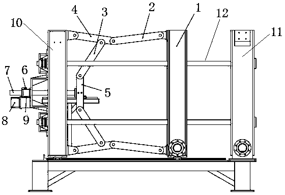
[0010] Such as figure 1 , 2 As shown, the mounting base 10 and the fixed mold 11 are fixed on the frame, and the movable mold 1 is installed between the mounting base 10 and the fixed mold 11 through the guide rod 12. It is characterized in that: a connecting rod mold locking mechanism is installed on the movable mold 1, and the The connecting rod clamping mechanism includes a support connecting rod 2, an extension rod 3, a connecting rod 4, an cross connecting rod 5, a driven gear 6, a driving screw 7, a driving motor 8 and a driving gear 9, and the driving motor is installed on the mounting base 10 8 and the driving screw 7, the driving gear 9 is installed on the output shaft of the driving motor 8, the driven gear 6 is installed on the driving screw 7, the driving gear 9 meshes with the driven gear 6, and the top of the driving screw 7 is connected to the cross connecting rod 5 The two ends of the cross connecting rod 5 are respectively connected to one end of the connecti...


PUM


Abstract

The invention discloses a connection rod mould locking mechanism. According to the connection rod mould locking mechanism, a rack is fixedly provided with a mounting seat (10) and a fixed mould (11), wherein a movable mould (1) is mounted between the mounting seat (10) and the fixed mould (11) by a guide rod (12); the mounting seat (10) is provided with a driving motor (8) and a driving screw rod (7); an output shaft of the driving motor (8) is provided with a driving gear (9); the driving screw rod (7) is provided with a driven gear (6); the top end of the driving screw rod (7) is connected with the center of a cross-shaped connection rod (5); the two ends of the cross-shaped connection rod (5) are respectively connected with one end of a connection rod (3); the other end of the connection rod (3) is connected onto a connection rod (4); one end of the connection rod (4) is connected with the mounting seat (10) and the other end of the connection rod (4) is connected with one end of a supporting connection rod (2); the other end of the supporting connection rod (2) is connected onto the movable mould (1). According to the connection rod mould locking mechanism, the connection rod is used for locking the mould and the bearing force of the connection rod is great so as to provide a reliable mould locking force; no energy is consumed and the production cost is reduced.

Description

technical field [0001] The invention relates to the mechanical field, in particular to a link mold locking mechanism. Background technique [0002] At present, in EPS equipment, hydraulic cylinders are used to clamp the mold, and the hydraulic motor must continue to work during mold clamping, which consumes a lot of energy. Contents of the invention [0003] The object of the present invention is to provide a link mold clamping mechanism, which adopts a link mold clamping method and does not need to consume energy during mold clamping. [0004] The technical solution of the present invention is: fix the mounting base and the fixed mold on the frame, and install the movable mold through the guide rod between the mounting base and the fixed mold. The connecting rod clamping mechanism includes supporting connecting rod, connecting rod, connecting rod, cross connecting rod, driven gear, driving screw, driving motor and driving gear. The driving motor and driving screw are ins...

Claims


Application Information

Patent Timeline
Patent Type & Authority Applications(China)
IPC IPC(8): B29C44/34
Inventor 郁震宇
Owner 郁震宇
Why Eureka
Try Eureka