

Molding machine
A technology of forming machine and toggle lever, applied in the field of forming machine, can solve the problems of high material cost, high manufacturing cost, thick tailstock, and high transportation cost, and achieve the effects of improving rigidity, precision and reliability.
- Summary
- Abstract
- Description
- Claims
- Application Information
AI Technical Summary
Problems solved by technology
Method used
Image

Examples
Embodiment Construction
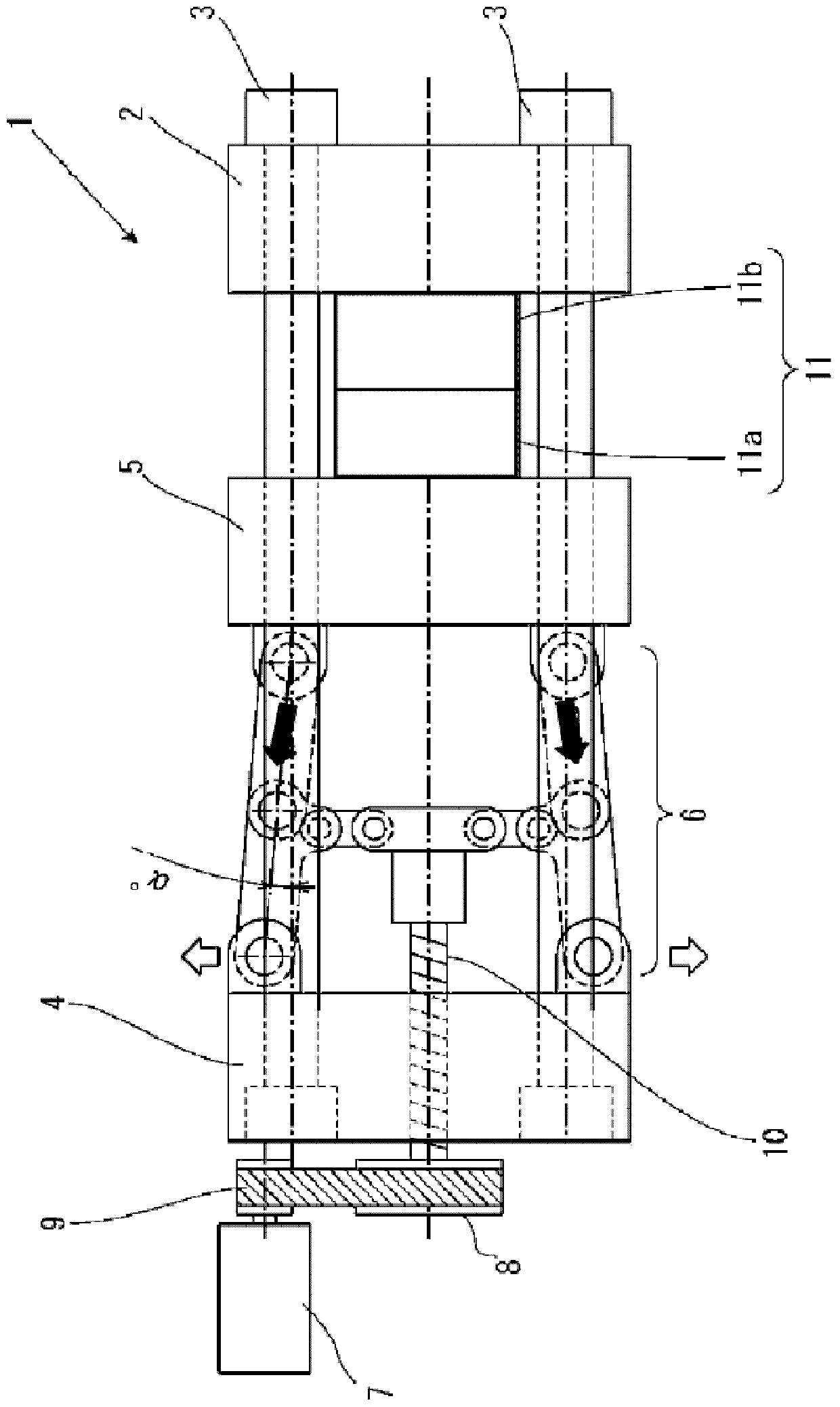
[0032] Next, examples of the best mode for carrying out the present invention will be described with reference to the injection molding machine of the accompanying drawings. Today, the present invention is not limited to injection molding machines but also includes die casting machines, and can be easily applied to devices other than those described in the examples within the range not departing from the gist of the invention. In the following description, an application example of a toggle mechanism applied to an injection molding machine will be described as an example.
[0033] In the specification of this application, the front-back, up-down, and left-right directions used refer to figure 1 direction shown. For the forward-backward direction, in figure 1 In , the direction toward the mold (right side) is referred to as the front, and the left side is referred to as the rear. The up and down direction refers to figure 1 In the up and down direction, the left and right d...
PUM
 Abstract
Description
Claims
Application Information