Self-adaptive clamping device of aircraft engine blade tip process table

A technology of clamping device and process table, which is applied in the direction of positioning device, clamping, manufacturing tools, etc., can solve the problems of clamping error and affecting the yield of blades, etc., and achieve the advantages of convenient use, high-efficiency mass production, and fast loading and unloading Effect

Active Publication Date: 2022-07-15
西安三航动力科技有限公司
View PDF13 Cites 2 Cited by
  • Summary
  • Abstract
  • Description
  • Claims
  • Application Information

AI Technical Summary

Problems solved by technology

In this state, the blade body is processed, even if the processing quality is good, when the clamping device is released, due to the existence of clamping stress, the blade will recover and deform, thereby introducing clamping error and affecting the yield of the blade

Method used


Image

  • Self-adaptive clamping device of aircraft engine blade tip process table
  • Self-adaptive clamping device of aircraft engine blade tip process table
  • Self-adaptive clamping device of aircraft engine blade tip process table

Examples


Embodiment 1

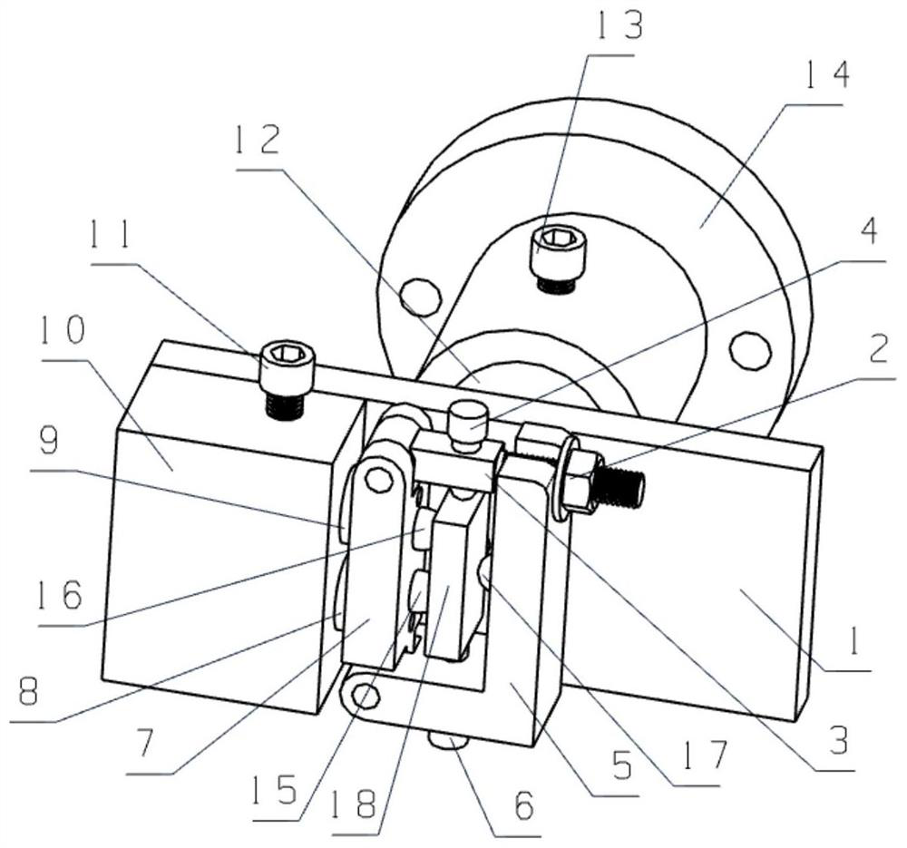
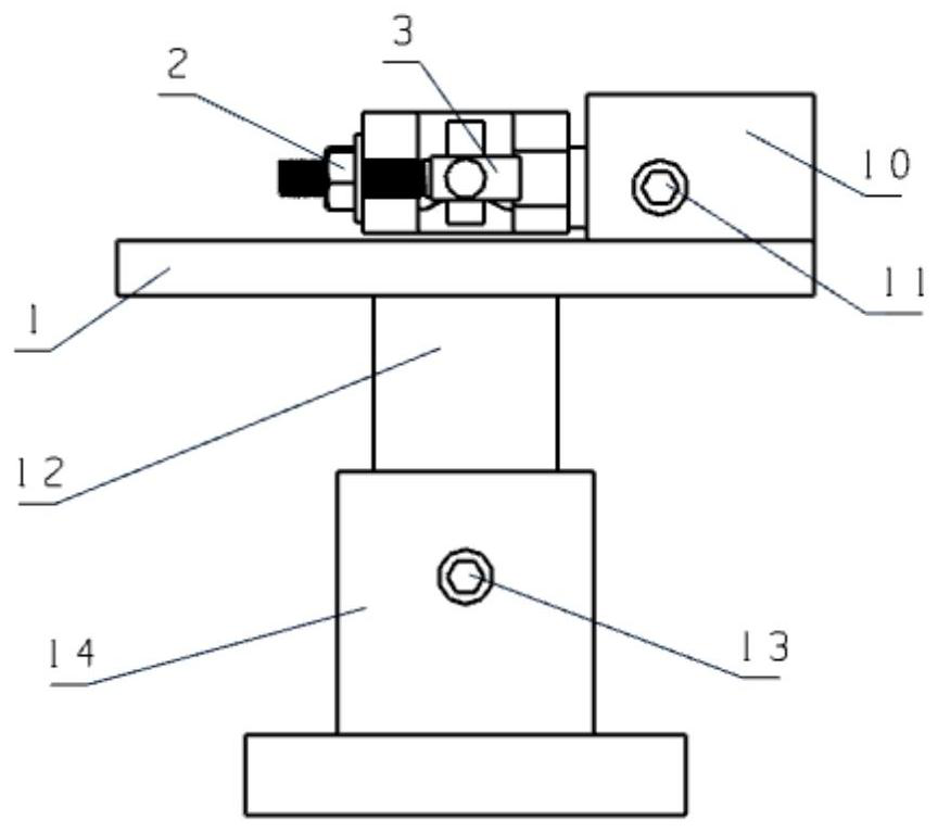
[0026] Example 1: as Figure 1 to Figure 4 As shown in the figure, an adaptive clamping device for a blade tip craft table of aero-engine blades, including a connecting plate 1, the connecting plate 1 is installed on a machine tool through a telescopic base, and the telescopic base includes a shaft sleeve 14 set on the machine tool, and is connected to One end of the shaft 12 is clearance fit, and is slidably arranged in the shaft sleeve 14. The connecting plate 1 is fixedly installed on the other end of the connecting shaft 12. The second top tightening screw 13 in the position;

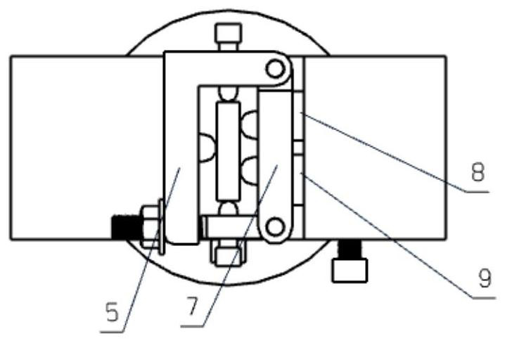
[0027] An ejector box 10 is fixedly installed on the connecting plate 1 , and the first clamping block 7 is installed on one side of the ejector box 10 through a pair of ejector bars in the ejector box 10 . The top rods are the first top rod 8 and the second top rod 9, one end of the first top rod 8 and the second top rod 9 are respectively parallel, and are slidably arranged in the two sliding gro...


PUM


Abstract

The invention relates to a self-adaptive clamping device for an aircraft engine blade tip process table, which is used for carrying out auxiliary support on the blade tip process table at the blade tip when a blade part is subjected to numerical control milling. When the device is used, along with tightening of the clamping nuts, the three ball head supporting nails on the clamping blocks on the two sides make contact with the two side faces of the blade tip process table one by one, the positions of the ejector rod and the connecting shaft are automatically adjusted, the positions of the ejector rod and the connecting shaft are fixed through the jacking screws, and self-adaptive clamping of the blade process table can be achieved. The problem that when blade tenon root positioning is used for clamping different blade tip process tables according to theoretical positions, clamping stress is introduced to blade tips due to the difference of the positions and the sizes of the blade tip process tables is solved, the device can improve the rigidity of a process system, meanwhile, the clamping stress is not introduced, and unstressed self-adaptive clamping of the blade tips is achieved. The device is simple in structure, convenient to operate and reliable in clamping force, and guarantees precision machining of the blade.

Description

technical field [0001] The invention relates to the field of blade numerical control machining, in particular to a clamping device for a blade tip craft table of aero-engine blades. Background technique [0002] As a key component of aero-engine, the processing quality of blade directly affects the overall performance of aero-engine. The structure of the blade is mainly divided into three parts: the blade body, the tenon and the edge plate. The blade body is the part of the blade with aerodynamic appearance; the tenon realizes the connection and fastening with other parts; the transition part between the blade and the tenon is the edge plate. With the improvement of the performance requirements of aero-engines, the design accuracy of the blades has been continuously improved, and the manufacturing requirements have become more and more strict. In order to improve the aerodynamic performance, the blade wall is thin, the blade body is a complex free-form surface with a long ...

Claims


Application Information

Patent Timeline
Patent Type & Authority Applications(China)
IPC IPC(8): B23Q3/06
CPCB23Q3/06B23Q3/062
Inventor 辛晓鹏胡创国汪磊许晓栋毛海江
Owner 西安三航动力科技有限公司
Why Eureka
Try Eureka