A swing guide wheel

A guide wheel, swinging technology, applied in the field of guide wheels, can solve the problems of laborious traction, inconvenient use, and wire rope slipping out, so as to save dragging time, save labor, and facilitate the effect of hauling goods

Inactive Publication Date: 2015-12-16
LEACREE CHENGDU
View PDF6 Cites 0 Cited by
  • Summary
  • Abstract
  • Description
  • Claims
  • Application Information

AI Technical Summary

Problems solved by technology

However, the main shaft of this guide wheel is fixed on the wall. When the position of the goods is not concentrated or the distance between the goods is far away, it will cause the steel wire rope in the groove to slip out of the groove, and it is very laborious during the traction process, increasing the load. It increases the workload of workers and is very inconvenient to use

Method used


Image

  • A swing guide wheel

Examples


Embodiment Construction

[0010] The present invention will be further described below in conjunction with accompanying drawing, protection scope of the present invention is not limited to the following:

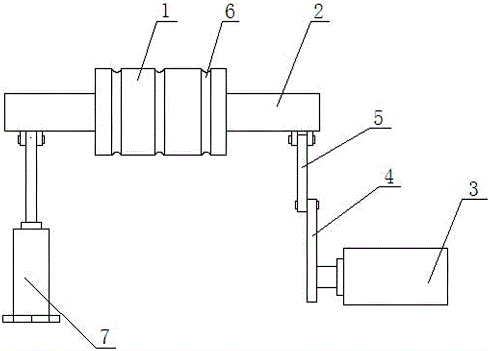
[0011] Such as figure 1 As shown, a swinging guide wheel includes a wheel body 1, a main shaft 2, a motor 3, a fixed rod 4, a connecting rod 5 and an oil cylinder 7. The wheel body 1 is installed on the main shaft 2, and the wheel body 1 is provided with There are multiple annular concave grooves 6, one end of the fixed rod 4 is arranged on the output shaft of the motor 3, the other end of the fixed rod 4 is hinged to one end of the connecting rod 5, and the other end of the connecting rod 5 is hinged to the main shaft 2 One end of the main shaft 2, the other end of the main shaft 2 is hinged with the piston rod of the oil cylinder 7, the oil cylinder 7 is arranged perpendicular to the main shaft 2, the motor 3 is arranged parallel to the main shaft 2 and the motor 3 is located below the main shaft 2...


PUM


Abstract

The invention discloses a swing type guide wheel which comprises a wheel body (1), a spindle (2), a motor (3), a fixing rod (4), a connecting rod (5) and an oil cylinder (7). The wheel body (1) is mounted on the spindle (2), multiple annular grooves (6) are formed in the wheel body (1), one end of the fixing rod (4) is arranged on an output shaft of the motor (3) while the other end of the fixing rod (4) is hinged to one end of the connecting rod (5), the other end of the connecting rod (5) is hinged to the other end of the spindle (2), the other end of the spindle (2) is hinged to a piston rod of the oil cylinder (7), the oil cylinder (7) is perpendicular to the spindle (2), the motor (3) is parallel to the spindle (2) and located below the same, and the oil cylinder (7) and the motor (3) are located on two sides of the wheel body (1). The swing type guide wheel has the advantages of simple structure, adjustable in direction of the annular grooves, convenience in use, simplicity in operation and saving in labor.

Description

technical field [0001] The invention relates to the technical field of guide wheels, in particular to a swing guide wheel. Background technique [0002] At present, the combination of guide wheels and wire ropes is mainly used for hauling goods. The main shaft of traditional guide wheels is generally fixed on the wall, and there are grooves on the guide wheels. When using the guide wheels to pull goods, first The wire rope is put on the groove, and then the head end of the wire rope is hung on the goods, and the end of the wire rope is installed on the hauler (such as a tractor, car), and when the hauler is started, the goods are dragged to a reasonable position. Therefore, the guide wheel has played the role of traction. However, the main shaft of this guide wheel is fixed on the wall. When the position of the goods is not concentrated or the distance between the goods is far away, it will cause the steel wire rope in the groove to slip out of the groove, and it is very la...

Claims


Application Information

Patent Timeline
Patent Type & Authority Patents(China)
IPC IPC(8): B66D1/00B66D1/36
Inventor 蒋斌
Owner LEACREE CHENGDU
Why Eureka
Try Eureka