Al technical title is built by PatSnap Al team. It summarizes the technical point description of the patent document.
An ultrasonic and paper technology, applied in the direction of measuring devices, using ultrasonic/sonic/infrasonic waves, instruments, etc., can solve the problems of high surface precision around the paper shaft, unfavorable industrial promotion and use, and inability to exert precision, so as to reduce disadvantages Effects of impact, lower center of gravity, and low production cost
Active Publication Date: 2017-01-25
HEBEI UNIV OF TECH
View PDF5 Cites 0 Cited by
Summary
Abstract
Description
Claims
Application Information
AI Technical Summary
This helps you quickly interpret patents by identifying the three key elements:
Problems solved by technology
Method used
Benefits of technology
Problems solved by technology
Due to the influence of receiving blind areas, ultrasonic waves in different frequency bands of different media, and different attenuation, ultrasonic waves cannot exert the best accuracy
(2) Although the eddy current principle can improve the measurement accuracy, due to the measurement principle, the surface accuracy of the winding shaft is very high, and the cost is high, which is not conducive to industrial promotion and use.
Obviously, the thickness of paper is not suitable for this method
Method used
Image
Click on the blue label to locate the original text in one second.
Reading with bidirectional positioning of images and text.
Examples
Embodiment Construction
[0027] The method of the present invention will be further described below in conjunction with the embodiments and accompanying drawings.
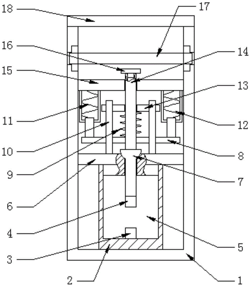
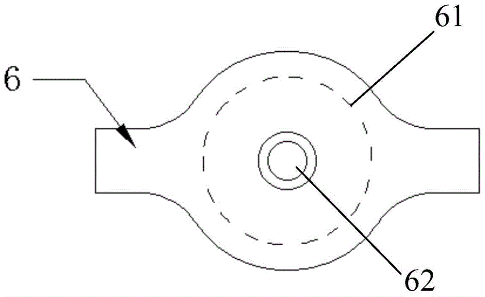
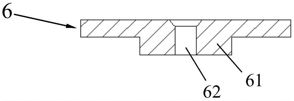
[0028] Ultrasonic paper thickness measuring device designed by the present invention (abbreviation thickness measuring device, see Figure 1-7 ), including bracket 1, tank body 2, upper ultrasonic probe 3, lower ultrasonic probe 4, tank upper cover 6, hemispherical valve 7, movable pin 8, spring 9, bracket with chute 10, left electromagnet 11, right electromagnetic Iron 12, limit pin 13, cylindrical tube 14, upper cover 15, measuring end face 16, winding paper shaft 17 and upper bracket 18.
[0029] The tank body 2 is placed on the bracket 1; the upper ultrasonic probe 3 is installed at the bottom of the tank body 2; the liquid 5 is housed inside the tank body 2; There is a spherical hole 62 in the middle of 61 that matches the hemispherical valve 7, and the tank upper cover 6 and the tank body 2 are connected together through the round p...
PUM
Abstract
The invention discloses an ultrasonic paper thickness measuring device. The ultrasonic paper thickness measuring device is characterized in that the ultrasonic paper thickness measuring device comprises a support, a tank body, an upper ultrasonic probe, a lower ultrasonic probe, a tank body upper cover, a semispherical valve, a movable pin, a spring, a support with a siding groove, a left electromagnet, a right electromagnet, a limiting pin, a cylindrical pipe, an upper cover, a measurement end face, a paper reel and an upper support. In the measuring process, the ultrasonic probes are in liquid all the time, ultrasonic frequency is high, and the accuracy of measurement results is high. The measuring end of the ultrasonic paper thickness measuring device is located at the lower end of the paper reel, in this way, the adverse effect on the measurement results due to the tank body internal liquid disturbance caused by the up and down movement of the lower ultrasonic probe can be reduced greatly, meanwhile, the gravity center of a system can be lowered, and the stability of the system can be improved. The ultrasonic paper thickness measuring device is simple in mechanical structure, low in manufacturing cost, high in measurement accuracy and reliable in working.
Description
technical field [0001] The invention relates to ultrasonic distance measuring technology, in particular to an ultrasonic thickness measuring device for measuring the thickness of paper products. Background technique [0002] Paper is an indispensable consumable in life and work, and its quality inspection has always been a relatively important issue. Because the thickness of the paper is generally thin, and some characteristics of the paper, such as uneven fiber distribution, many gaps, easy to be deformed by external force, and cannot be immersed in liquid, etc., the measurement work is very difficult. For thickness measurement, traditional measurement methods are divided into contact measurement and non-contact measurement. The current paper thickness detection generally adopts a non-contact method. Non-contact methods are divided into ultrasonic measurement principle thickness measurement, eddy current effect principle thickness measurement and Hall principle thickness ...
Claims
Application Information
Patent Timeline
Application Date:The date an application was filed.
Publication Date:The date a patent or application was officially published.
First Publication Date:The earliest publication date of a patent with the same application number.
Issue Date:Publication date of the patent grant document.
PCT Entry Date:The Entry date of PCT National Phase.
Estimated Expiry Date:The statutory expiry date of a patent right according to the Patent Law, and it is the longest term of protection that the patent right can achieve without the termination of the patent right due to other reasons(Term extension factor has been taken into account ).
Invalid Date:Actual expiry date is based on effective date or publication date of legal transaction data of invalid patent.