Optical Plate With Microstructures

一种微结构、光学板的技术,应用在光学板领域,达到降低热点问题、提升混光程度的效果

Inactive Publication Date: 2014-07-09
CHI MEI CORP
View PDF4 Cites 3 Cited by
  • Summary
  • Abstract
  • Description
  • Claims
  • Application Information

AI Technical Summary

Problems solved by technology

However, when the light source enters the optical plate from the side of the base surface 11, there will be a darker area, that is, a hot spot (hotspot) at the intersection of the light rays of the adjacent two LED lamps of the light source.

Method used


Image

  • Optical Plate With Microstructures
  • Optical Plate With Microstructures
  • Optical Plate With Microstructures

Examples


Embodiment Construction

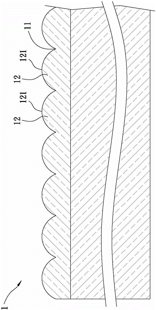
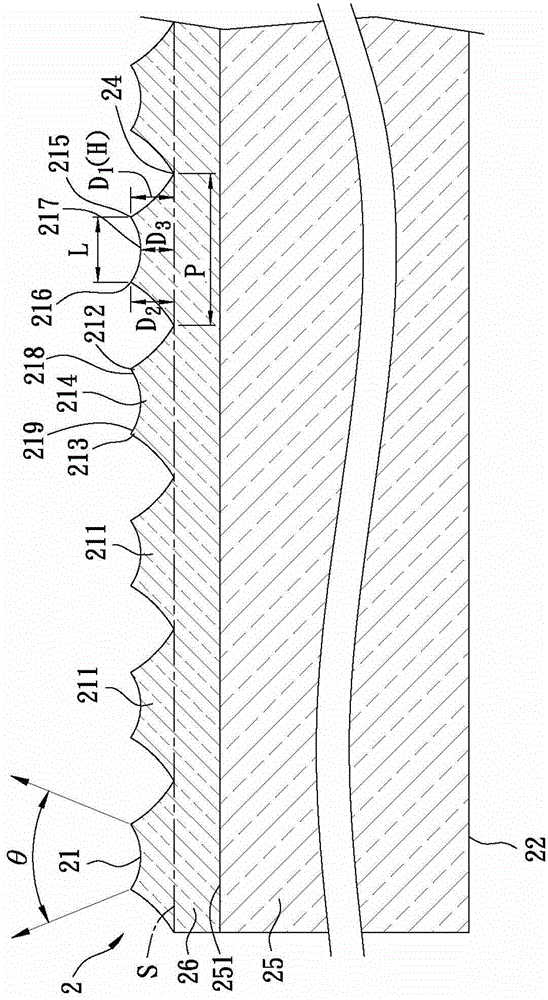
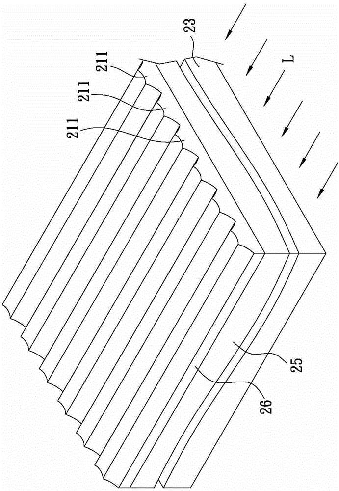
[0029] refer to figure 2 , image 3 , the first preferred embodiment of the optical plate with microstructures of the present invention comprises a substrate 2 .

[0030] The substrate 2 includes a light-emitting surface 21, a back surface 22 opposite to the light-emitting surface 21, and a side surface 23 connecting the light-emitting surface 21 and one side of the back surface 22. The light-emitting surface 21 is formed with a plurality of parallel microstructures 211, And the microstructures 211 extend in the same direction.

[0031] Wherein, the vertical section of each microstructure 211 extending in parallel has a first convex portion 212 and a second convex portion 213 spaced apart from each other, and a concave portion 214 connecting the first convex portion 212 and the second convex portion 213, wherein, The vertical section of each microstructure 211 refers to the direction perpendicular to the extending direction of the microstructure.

[0032] The microstructur...


PUM


Abstract

An optical plate with microstructures includes a substrate having a light emitting surface, a rear surface opposite to the light emitting surface, and a side surface connecting one side of the light emitting surface and the rear surface. A plurality of microstructures that extend parallelly are formed on the light emitting surface, wherein the vertical cross-section shape of each of the parallelly extending microstructures includes first and second convex portions which are separated from each other, and a concave portion for connecting the first and second convex portions. The optical plate with microstructures enables the light-emitting angle and light mixing degree to be improved by the first and second convex portions of each microstructure and the concave portion between the first and second convex portions.

Description

technical field [0001] The invention relates to an optical plate, in particular to an optical plate with a microstructure. Background technique [0002] refer to figure 1 , the main purpose of the optical plate is to change and guide the traveling direction of light. The current optical plate 1 includes a base surface 11 and a plurality of microstructures 12 formed on the base surface. [0003] The microstructures 12 are adjacent to each other in parallel, and each microstructure 12 includes a convex portion 121, the cross-sectional area of ​​the convex portion 121 gradually decreases away from the base surface 11, and the side cross-sectional schematic diagram of the convex portion 121 Can be triangular or arc-shaped. For example, the protrusion 121 of the microstructure 12 can be a triangle or the like. [0004] The optical plate 1 is a light guiding medium in a backlight module (not shown in the figure), and when applied to an edge type backlight module, it can guide t...

Claims


Application Information

Patent Timeline
Patent Type & Authority Applications(China)
IPC IPC(8): G02B6/00G02B5/02G02B1/04
CPCB29D11/0073B29D11/00288G02B6/0038G02B6/0065
Inventor 萧琇方蔡爵仰郭俊良陈信宏黄中平
Owner CHI MEI CORP
Why Eureka
Try Eureka