Back light module and liquid crystal display device

A backlight module and light mixing technology, applied in optics, nonlinear optics, instruments, etc., can solve the problem of uneven light mixing of light-emitting diodes, and achieve the effect of uniform color mixing

Inactive Publication Date: 2007-06-27
INNOCOM TECH SHENZHEN +1
View PDF0 Cites 1 Cited by
  • Summary
  • Abstract
  • Description
  • Claims
  • Application Information

AI Technical Summary

Problems solved by technology

[0007] In order to solve the problem of uneven light mixing of LEDs in the above-mentioned backlight module, it is necessary to provide a backlight module that can improve the light mixing effect of LEDs.

Method used


Image

  • Back light module and liquid crystal display device
  • Back light module and liquid crystal display device

Examples


Embodiment Construction

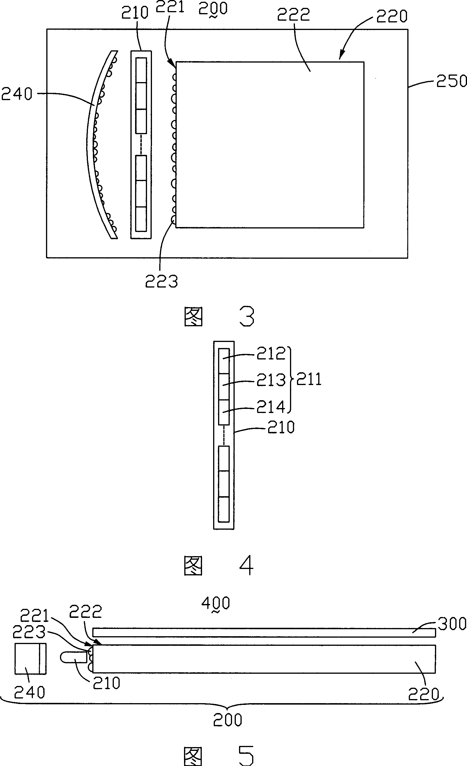
[0017] Please refer to FIG. 3 , which is a structural diagram of a preferred embodiment of the backlight module of the present invention. The backlight module 200 includes a light source 210 , a light guide plate 220 , a reflection device 240 with a reflection surface, and an outer frame 250 . The outer frame 250 accommodates the light source 210 , the light guide plate 220 and the reflection device 240 .

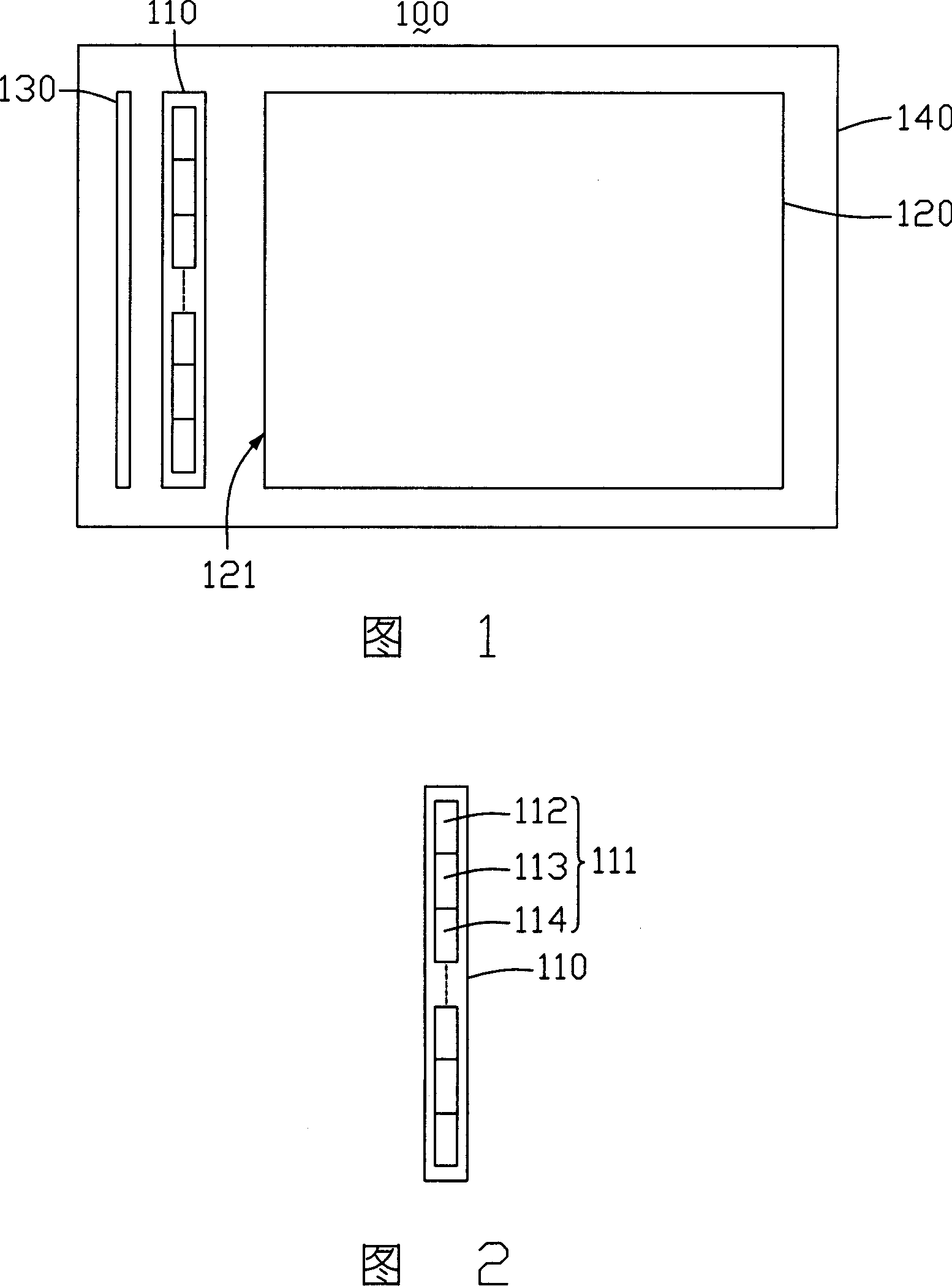
[0018] The light guide plate 220 includes a light incident surface 221 and a light exit surface 222 adjacent to the light incident surface 221, the reflective device 240 is arranged opposite to the light incident surface 221 of the light guide plate 220, and the light source 210 is disposed on the reflective device. 240 and the light guide plate 220. Please also refer to FIG. 4 , which is a schematic structural diagram of the light source 210 . The light source 210 includes a plurality of LED units 211 . Each LED unit 211 includes a red LED 212 , a green LED 213 and a bl...


PUM


Abstract

The disclosed backlight module includes multiple pieces of light emitting diode (LED), and a light guide plate. The light guide plate includes a light entering face. The multiple pieces of LED are setup in relation to the light entering face. The multiple pieces of LED include red LED, green LED, and blue LED. Multiple light mixing structures are setup on the light entering face. The backlight module raises effect of mixing light of LEDs. The invention also discloses the liquid crystal display device of using the backlight module.

Description

【Technical field】 [0001] The invention relates to a backlight module and a liquid crystal display device using the backlight module. 【Background technique】 [0002] Liquid crystal display devices have the characteristics of thinness, low power consumption, and less radiation, and are widely used in monitors, LCD TVs, mobile phones, and portable computers, and have become the mainstream of displays. demanding. Since the liquid crystal itself does not emit light, a backlight module is required to provide a light source for it. [0003] Please refer to FIG. 1 , which is a schematic structural diagram of a prior art backlight module. The backlight module 100 includes a light source 110 , a light guide plate 120 , a reflection device 130 and a back frame 140 . The back frame 140 accommodates the light guide plate 120 , the light source 110 and the reflection device 130 . The light guide plate 120 has a light incident surface 121 , the reflection device 130 is disposed opposit...

Claims


Application Information

Patent Timeline
Patent Type & Authority Applications(China)
IPC IPC(8): G02F1/13357G02F1/1335G02B5/02H01L33/00
Inventor 杨坤宪石安
Owner INNOCOM TECH SHENZHEN
Why Eureka
Try Eureka