Method for determining weak rods in truss structures of hoisting and conveying machinery

A technology for lifting and transporting machinery and truss structures, which is applied in special data processing applications, instruments, electrical digital data processing, etc. The effect of increasing market competitiveness

Inactive Publication Date: 2014-07-09
CHANGAN UNIV
5 Cites 8 Cited by

AI-Extracted Technical Summary

Problems solved by technology

[0003] Aiming at the deficiencies of the prior art, the purpose of the present invention is to provide a method for determining the weak members of the truss structure in the hoisting and transporting machinery, and to judge whether the members have...

Abstract

The invention provides a method for determining weak rods in truss structures of hoisting and conveying machinery. By judging whether the rods reach critical conditions or not according to practical stress states of the rods, the problem that only part of the rods are checked without regard to bending moments of ends of the pressed rods in the prior art is solved. Practical stresses of all rods are extracted in binary iterative analysis in each time, whether each rod reaches the critical conditions or not is judged, stretch bent rods are judged according to strength theory, pressure bent rods are judged according to stability of the pressure bent rods, and the rods are repeatedly loaded until a certain rod or a certain batch of rods reaches the critical conditions. Therefore, using the method can determine positions of all weak rods, rod bearing conditions and the degree of each rod approaching to the critical conditions, design direction of local reinforcement of the truss structures is indicated, potential risks are eliminated at the design stage, and market competitiveness of products is improved.

Application Domain

Special data processing applications

Technology Topic

Strength theoryBending moment +7

Image

  • Method for determining weak rods in truss structures of hoisting and conveying machinery
  • Method for determining weak rods in truss structures of hoisting and conveying machinery
  • Method for determining weak rods in truss structures of hoisting and conveying machinery

Examples

  • Experimental program(1)

Example Embodiment

[0072] Examples:
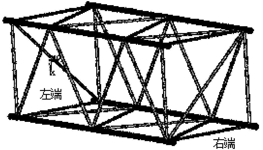
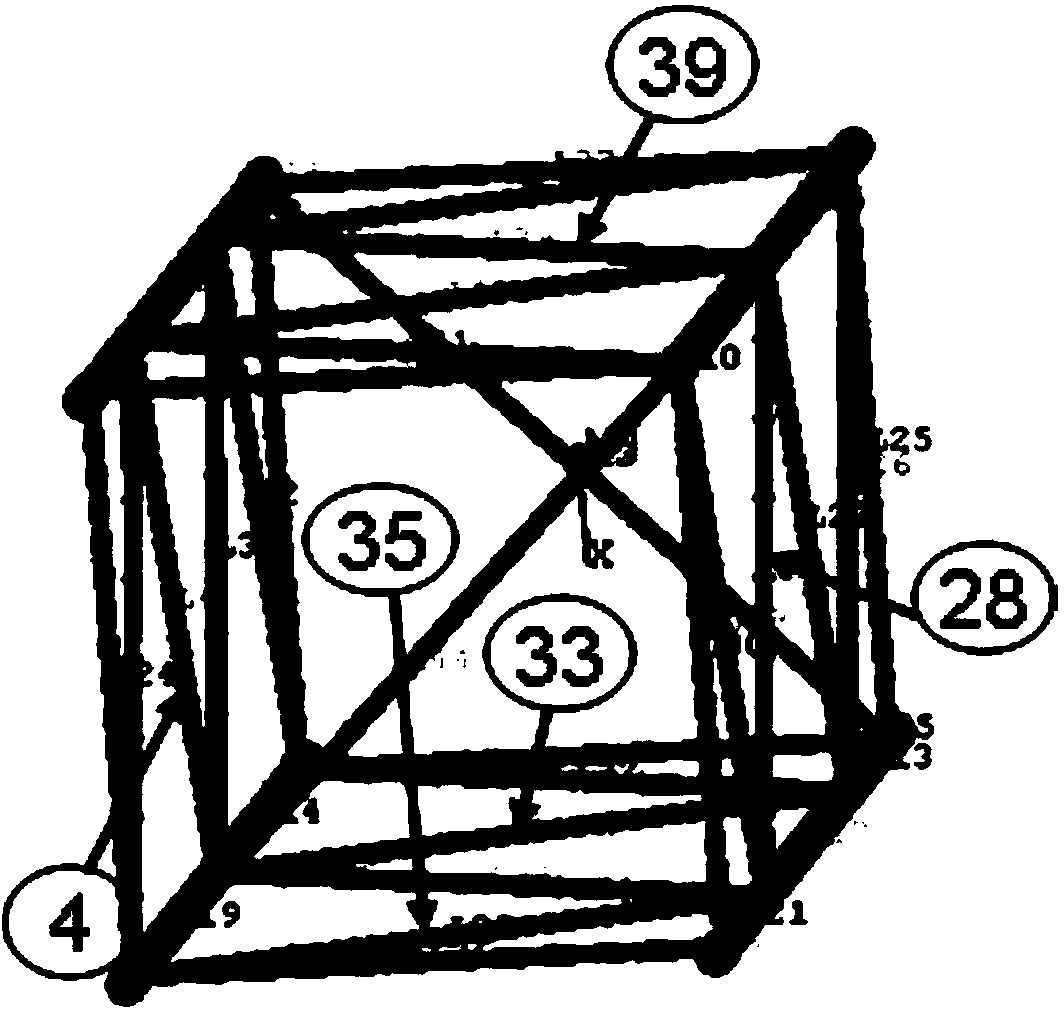
[0073] The truss arm in this embodiment is as Picture 11 Shown is a truss boom section welded from round steel pipes. The four main chords at the right end are fixed at the ends, and the left end is subjected to torque. Two symmetrical oil cylinders generate thrust to apply torque, and the weak link of the structure is analyzed and determined. The yield limit of the main chord material of the boom section is 770MPa, the yield limit of the abdominal tube material is 245MPa, the density is 7850kg/m3, and the elastic modulus is 2.1×10 11 , Poisson's ratio is 0.3.
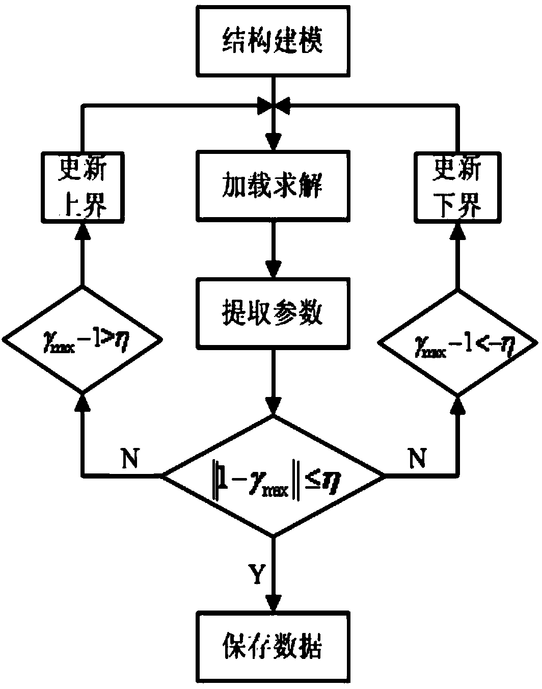
[0074] The method for determining the weak members of the truss structure in the above-mentioned lifting and transporting machinery is carried out according to the following steps:
[0075] Step 1: Use the finite element software ANSYS to perform parametric modeling. The right end of the boom section restricts all degrees of freedom, and the left end uses the mass point Mass21 to couple the ends of the four main chords together as a torque application point. Use the pipe element PIPE16 for network Grid division, the parameterized model built is such as figure 2 Shown.
[0076] Step 2: Set the torque interval applied to the boom section as [0, 1000]t·m;
[0077] Step 3: Take the median 500t·m of the interval [0,1000]t·m as the applied torque, and perform the finite element analysis and solution of the boom section;
[0078] Step 4: Extract the axial tensile stress or compressive stress of each rod, and obtain γ according to the following formula j ,
[0079]
[0080] Step 5: Right γ j Sort in descending order, whichever is the largest γ max =max{γ j }, and determine γ j Does it satisfy the following formula:
[0081] ||1-γ max ||≤η
[0082] In the formula, η is a positive small quantity, take η = 0.0001, the symbol "||·||" means to find the absolute value;
[0083] Step 6: When ||1-γ max ||≤η, then γ max The corresponding bar reaches its critical state, stop loading, and save γ max Corresponding member number and corresponding load value;
[0084] Step 7: When||1-γ max ||>η, then γ max If the corresponding rod has not reached its critical state or far exceeds the critical state, go to step 8 or step 9 to adjust the load;
[0085] Step 8: If γ max -1<-η, which indicates that the current load is too small and the member has not reached the critical state. The median value of the current dichotomy is used as the lower bound of the interval, and the upper bound remains unchanged, forming a new load interval [a′,b], go to Step 10;
[0086] Step 9: If γ max -1> η, indicating that the current load is too large, and the member has already reached the critical state, the current median of the dichotomy is used as the upper bound of the interval, and the lower bound remains unchanged, forming a new load interval [a,b′], go to step 10;
[0087] Step 10: Repeat the iterative process from step 3 to step 9 above, until a certain rod or batch of rods in the boom meets the iteration termination condition||1-γ max ||≤η, then γ j The corresponding load is the critical load of a bar or a group of bars in the boom structure when it reaches a critical state.
[0088] The information of the weak member of the boom section under the action of torque obtained by the above steps of the method of the present invention is shown in Table 1. image 3 The location of the corresponding weak rod is marked. It can be seen from Table 1 that the γ values ​​of the first four rods are all close to 1, and the difference between them is very small, indicating that these rods are in a critical state. Theoretically, the rod 33 should reach its critical state first, and is most likely to fail before other rods. The torque corresponding to its instability is about 14.6t·m. Taking into account the residual stress existing in the actual boom section, the variability of the steel pipe material characteristic parameters and the influence of the analysis model error, it can be considered that any member in Table 1 may fail in the first stage and can be regarded as weak The rods are all pressure-bending rods. Figure 4 Is the Von mises stress of the boom section when the rod 33 reaches the critical state, the maximum stress is 206MPa; Figure 5 It is the Von mises stress cloud diagram of the weak member 33. The maximum Von mises stress is 200 MPa, which is located at the end of the member. Because the end is subjected to bending moment, the force condition is more complicated; Image 6 It is the axial compressive stress generated by the axial pressure of the rod 33, that is, does not contain the stress caused by the bending moment, and its value is -169MPa. It can be seen that when the rod 33 undergoes compression and bending instability, the axial compressive stress value is less than the yield limit of the material 245MPa ; Figure 7 Is the shear stress in the x′y′ direction of the member 33, the maximum shear stress is only 3.94MPa, which can be ignored; Figure 8 Is the bending moment diagram of the rod 33 in the x'direction in the element coordinate system; Picture 9 Is the bending moment diagram of the rod 33 in the y'direction in the element coordinate system; Picture 10 It is the bending moment diagram of the rod 33 in the z'direction in the element coordinate system.
[0089] Effect verification: In order to facilitate the comparison of the weak member determined by the method of the present invention with the weak member produced by the actual test, the truss arm in the embodiment is subjected to the actual test under the same parameter conditions as the embodiment, and the results are as follows Picture 11 As shown, Picture 11 The corresponding position of the weak member analyzed by the method of the present invention in the actual test is marked in. by Picture 11 The degree of deformation of the rod after instability can be known. The first rod to fail should be one of the ones listed in Table 1, indicating that the weak rod analyzed by the method of the present invention is consistent with the test results.
[0090] Table 1 The relevant information of the weak member in the torsion test of the boom section determined by the method of the present invention
[0091] Serial number

PUM

no PUM

Description & Claims & Application Information

We can also present the details of the Description, Claims and Application information to help users get a comprehensive understanding of the technical details of the patent, such as background art, summary of invention, brief description of drawings, description of embodiments, and other original content. On the other hand, users can also determine the specific scope of protection of the technology through the list of claims; as well as understand the changes in the life cycle of the technology with the presentation of the patent timeline. Login to view more.

Similar technology patents

Intelligent household plane heating body

InactiveCN105444249AThe overall design is ingeniousImprove market competitiveness
Owner:林晓生

Nutritional soybean milk and preparation process thereof

Owner:安徽省徽州印象农业科技有限责任公司

Classification and recommendation of technical efficacy words

Why Eureka
Try Eureka