Muffler transmission loss testing system and muffler transmission loss testing method for aiming at aerodynamic noise

A technology of transmission loss and aerodynamic noise, applied in the direction of vehicle testing, machine/structural component testing, instruments, etc., to achieve the effect of convenient operation, high precision and simple structure

Pending Publication Date: 2017-02-08
BRILLIANCE AUTO
View PDF0 Cites 16 Cited by
  • Summary
  • Abstract
  • Description
  • Claims
  • Application Information

AI Technical Summary

Problems solved by technology

[0006] The purpose of the present invention is to provide a muffler transmission loss test system and method for aerodynamic noise, which solves many shortcomings of traditional devices and methods in practical applications, and has simple structure, high test accuracy and convenient operation

Method used


Image

  • Muffler transmission loss testing system and muffler transmission loss testing method for aiming at aerodynamic noise
  • Muffler transmission loss testing system and muffler transmission loss testing method for aiming at aerodynamic noise
  • Muffler transmission loss testing system and muffler transmission loss testing method for aiming at aerodynamic noise

Examples


Embodiment 1

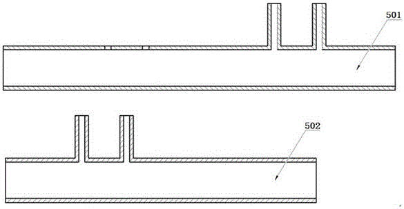
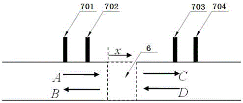
[0030] A muffler transmission loss test system for aerodynamic noise such as figure 1 As shown, it includes frequency conversion centrifugal fan 1, fan noise muffler 2, air flow sensor 3, air pressure sensor 4, standing wave tube 5, muffler to be tested 6, microphone group 7, electronic air pressure relief valve 8, pressure relief valve muffler 9. A / D conversion board 10, gain amplifier 11 and computer 12. The air outlet of the variable frequency centrifugal fan 1 is connected to the intake end of the fan noise muffler 2; the electronic air pressure relief valve 8 and the pressure relief valve muffler 9 are installed in series on the side branch pipe of the centrifugal fan 1; one end of the front pipe of the standing wave pipe 5 Connect the air outlet end of the fan noise muffler 2, and the other end is connected to the inlet end of the muffler 6 to be tested; the air outlet end of the muffler 6 to be tested is connected to one end of the rear pipe of the standing wave tube 5;...

Embodiment 2

[0044] The difference between the muffler transmission loss test system for aerodynamic noise in this embodiment and Embodiment 1 is that, in addition to performing amplitude calibration on each microphone, phase calibration should also be carried out so that the lag of the four microphones at the same time The angle is equal to 0, so that they are synchronized in phase, so that the sound pressure signal collected by the microphone is more accurate, and the measurement error is eliminated to the greatest extent.

Embodiment 3

[0046] The difference between the muffler transmission loss test system for aerodynamic noise in this example and Example 1 is that in order to ensure the accuracy and consistency of the test results, the temperature, humidity, and atmospheric pressure levels of the test environment should be kept stable, and there should be no electromagnetic interference around And the background noise should be less than 36 decibels.


PUM


Abstract

The invention provides a muffler transmission loss testing system and a muffler transmission loss testing method for aiming at aerodynamic noise, and particularly relates to a system and a method for testing aerodynamic noise muffling capability of an automotive intake/exhaust muffler. The muffler transmission loss testing system comprises a variable-frequency centrifugal fan, a fan noise muffler, an air flow sensor, an air pressure sensor, a standing wave tube, a microphone set, an electronic air pressure relief valve, a pressure relief valve muffler, an analog/digital conversion board, a gain amplifier and a computer. The muffler transmission loss testing method comprises the steps of fixing a to-be-tested muffler on a table; starting the testing system and performing initialization setting on the testing system; monitoring an air flow and pressure in the standing wave tube; controlling the fan and the pressure relief valve for sustaining the flow and the pressure in the system; testing a sound pressure value at a corresponding position in the standing wave tube; calculating the transmission loss; and outputting a result. The muffler transmission loss testing system and the muffler transmission loss testing method have advantages of simple structure, convenient operation and high accuracy. The muffler transmission loss testing system and the muffler transmission loss testing method fill in gaps in testing the aerodynamic noise transmission loss of the automotive intake/exhaust system.

Description

technical field [0001] The invention relates to the field of automobile acoustic performance testing, in particular to a muffler transmission loss testing system and method for aerodynamic noise. Background technique [0002] With the rapid growth of car ownership, the problem of car noise pollution is becoming more and more serious, and the corresponding noise control regulations are becoming more and more stringent. The intake and exhaust noise of the engine is the main noise source of the car, and the muffler with a reasonable structure is the most effective and simplest way to reduce the noise of the whole vehicle. [0003] Noise elimination is the main function of the muffler. When designing a muffler, it is necessary to know its specific muffler effect. Transmission loss is the most direct technical index to measure the noise reduction ability of a muffler, and its definition is the amount of energy lost during the transmission of sound through the microphone. [000...

Claims


Application Information

Patent Timeline
Patent Type & Authority Applications(China)
IPC IPC(8): G01M17/007
CPCG01M17/007
Inventor 徐勇王晖赵珩
Owner BRILLIANCE AUTO
Why Eureka
Try Eureka