
Digital Circuit Experimental Device and Experimental Method

An experimental device and digital circuit technology, applied in educational appliances, instruments, teaching models, etc., can solve problems such as wrong connection, difficult for students to judge and find the cause, and difficult for beginners to establish the concept of digital circuit design. To achieve the effect of simple connection, avoiding interference, wrong connection and poor contact

Inactive Publication Date: 2015-12-09
SHANDONG NORMAL UNIV
View PDF10 Cites 0 Cited by
  • Summary
  • Abstract
  • Description
  • Claims
  • Application Information

AI Technical Summary

Problems solved by technology

The disadvantages of this method are: 1. Due to lack of experience, students often make wrong connections
2. The experiment box has been used for a long time, and there will be poor contact between the connection line and the socket. It is difficult for students to judge and find out the reason
3. If the frequency is high, improper selection of the length of the connection will also affect the normal operation of the circuit
4. This connection method is not used in actual work, and is generally completed by using printed circuit board (PCB) design
Its disadvantage is: students can't see the real logic chips, such as 74LS00, 74LS138, 74LS374, etc. during the experiment, it is just a simulation feeling, it is difficult for beginners to establish the concept of digital circuit design
Its disadvantages are: 1. Students cannot see real logic chips during simulation, such as 74LS00, 74LS138, 74LS374, etc. It is difficult for beginners to establish the concept of digital circuit design
2. During the experiment, the students still use the traditional connection method
Its disadvantage is that students cannot see real logic chips, such as 74LS00, 74LS138, 74LS374, etc. during the experiment, it is just a simulation feeling, and it is difficult for beginners to establish the concept of digital circuit design

Method used


Image

  • Digital Circuit Experimental Device and Experimental Method
  • Digital Circuit Experimental Device and Experimental Method
  • Digital Circuit Experimental Device and Experimental Method

Examples


Embodiment Construction

[0032] The present invention is described in detail below in conjunction with accompanying drawing:

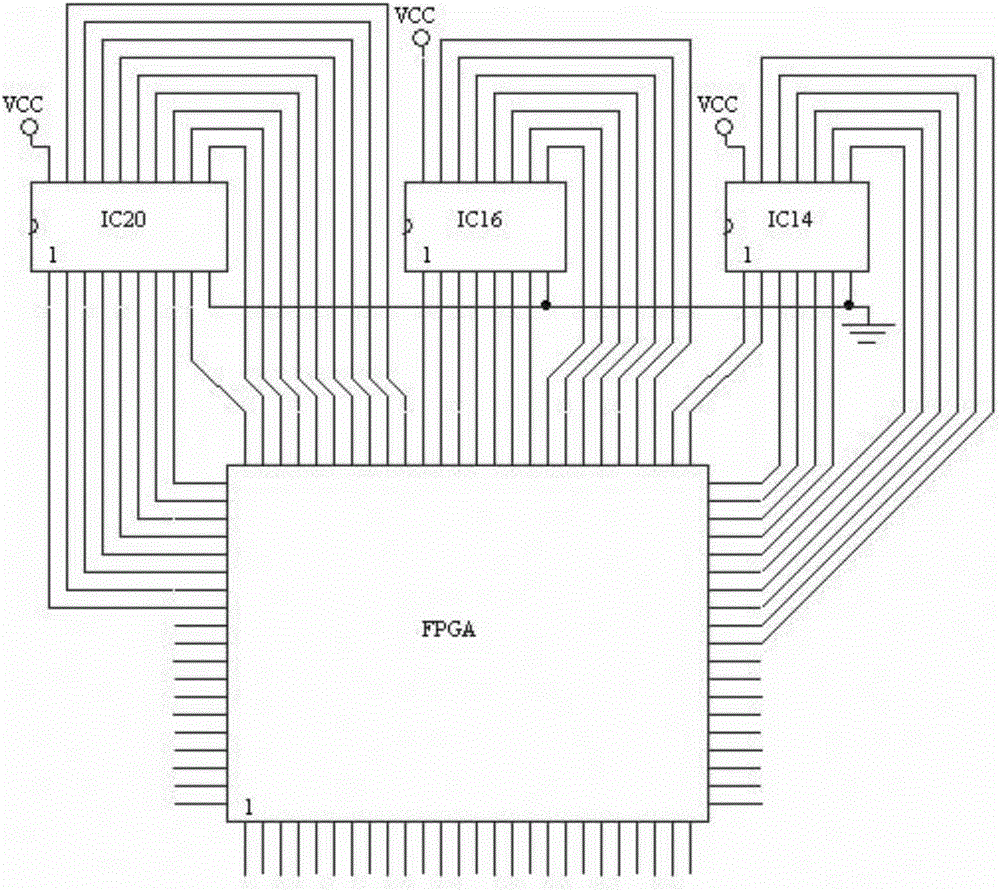
[0033] like figure 1 As shown, the digital circuit experimental device includes an FPGA chip, the FPGA chip is connected to the upper computer for communication, the FPGA chip is placed in the experiment box, and the connection between the pins of the FPGA chip and the pins of the IC socket is routed by the printed circuit board PCB To realize, the FPGA chip is connected to several IC sockets, and the power supply and ground of the IC sockets are respectively connected to the power supply and ground of the corresponding experimental box.

[0034] The IC socket is a socket for connecting 74LS series integrated circuits.

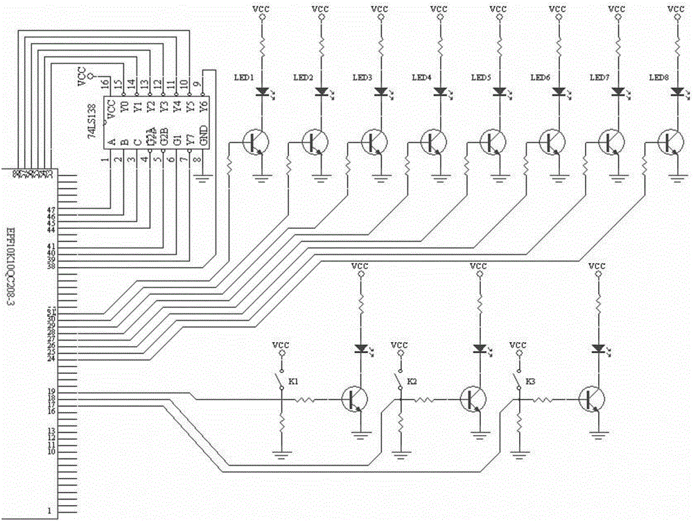
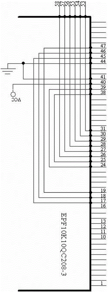
[0035] The experimental device also includes a switch circuit and a display circuit, the switch circuit is connected with the input terminal of the FPGA chip, the display circuit is connected with the output terminal of the FPGA chip, and the switch circuit a...


PUM


Abstract

The invention discloses a digital circuit experiment device and experiment method. The digital circuit experiment device comprises an FPGA chip which is in communication with an upper computer and placed in an experiment box, connecting wires between pins of the FPGA chip and pins of IC sockets are achieved through wiring of a PCB, the FPGA chip is connected with the multiple IC sockets, and a power source of the IC sockets and the ground are connected with a corresponding power source for supplying power to the experiment box and the ground respectively. Due to switching on and switching off of a switch arranged in a switch circuit, various data are input into an integrated circuit, and various corresponding data output by the integrated circuit are displayed on a display circuit. Interference, error wire connection and poor contact caused by chaos wire connection of metal wires can be avoided. The small-scale integrated circuit of the digital circuit experiment box is reserved, and a beginner can establish the logic circuit concept easily. The wire connection relation of a conducted experiment can be reserved for the upper computer, and convenience is provided for repeatedly verifying the experiment and completing a half-finished experiment.

Description

technical field [0001] The invention relates to a digital circuit experiment device and an experiment method. Background technique [0002] When teaching digital system courses such as "Digital Circuits", students need to do corresponding digital circuit experiments. The traditional experimental method is to insert the required experimental integrated circuit into the socket of the integrated circuit of the experimental box, and then connect them with wires as required to form the required experimental circuit. The disadvantages of this method are: 1. Due to lack of experience, students often make wrong connections. 2. If the experiment box is used for a long time, there will be poor contact between the connection line and the socket, and it is difficult for students to judge and find out the reason. 3. If the frequency is high, improper selection of the length of the connection will also affect the normal operation of the circuit. 4. This connection method is not used in...

Claims


Application Information

Patent Timeline
Patent Type & Authority Patents(China)
IPC IPC(8): G09B23/18
Inventor 杨峰翟临博张佳
Owner SHANDONG NORMAL UNIV
Learn More