Cylindrical rotating plate permanent magnet coupler

A permanent magnet coupler, turntable technology, applied in electrical components, electromechanical devices, electromechanical transmission devices, etc., can solve the problems of lack of isolation vibration, energy saving, power waste, etc., to achieve simple installation and debugging, increase coupling area, avoid shaft The effect of thrust

Active Publication Date: 2014-07-09
QINGDAO SPRING ENERGY TECH
View PDF5 Cites 9 Cited by
  • Summary
  • Abstract
  • Description
  • Claims
  • Application Information

AI Technical Summary

Problems solved by technology

[0002] The existing motor systems basically have the phenomenon of large horses and small carts, and the waste of electric energy is serious, and the traditional mechanical coupling inevitably transmits vibration from one end to the other through the coupling, which obviously does not have the ability to isolate vibration and Energy-saving performance, the "Twelfth Five-Year Plan for Energy Conservation and Emission Reduction" clearly proposes to use energy-saving technologies such as permanent magnet eddy current flexible transmission to optimize system operation and control, and improve the overall operating efficiency of the system

Method used


Image

  • Cylindrical rotating plate permanent magnet coupler
  • Cylindrical rotating plate permanent magnet coupler
  • Cylindrical rotating plate permanent magnet coupler

Examples


Embodiment 1

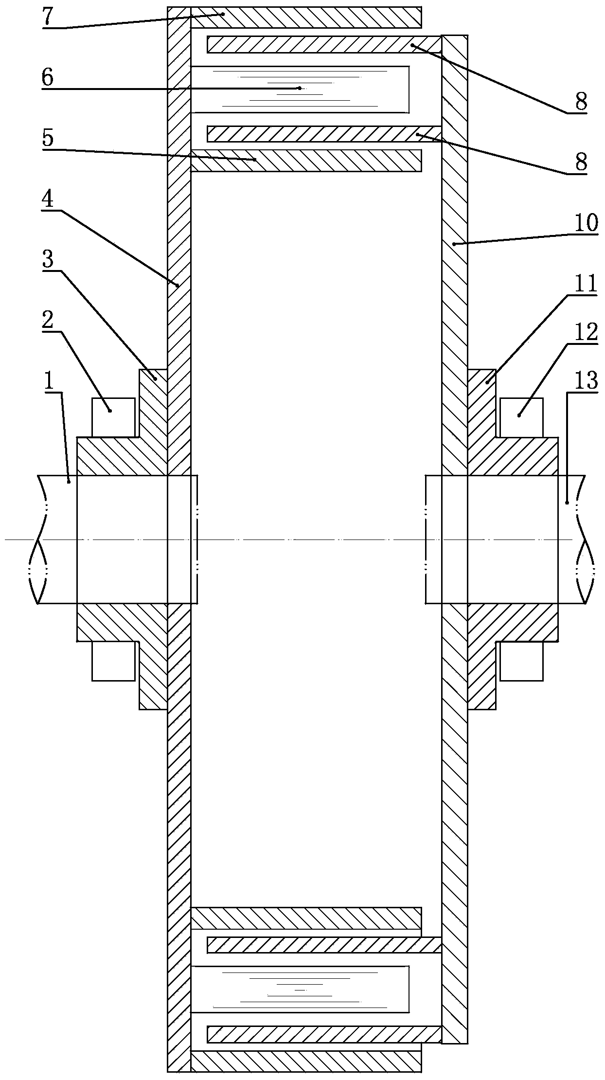
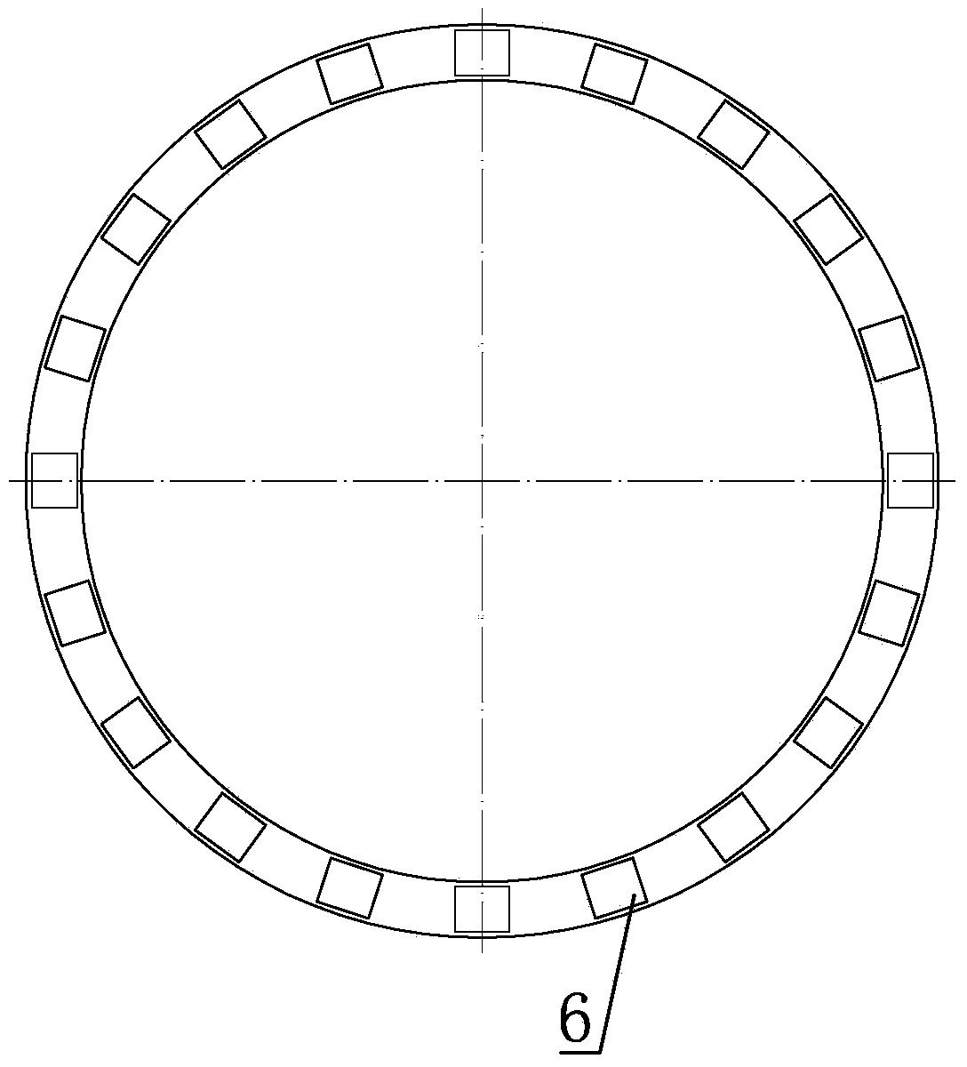
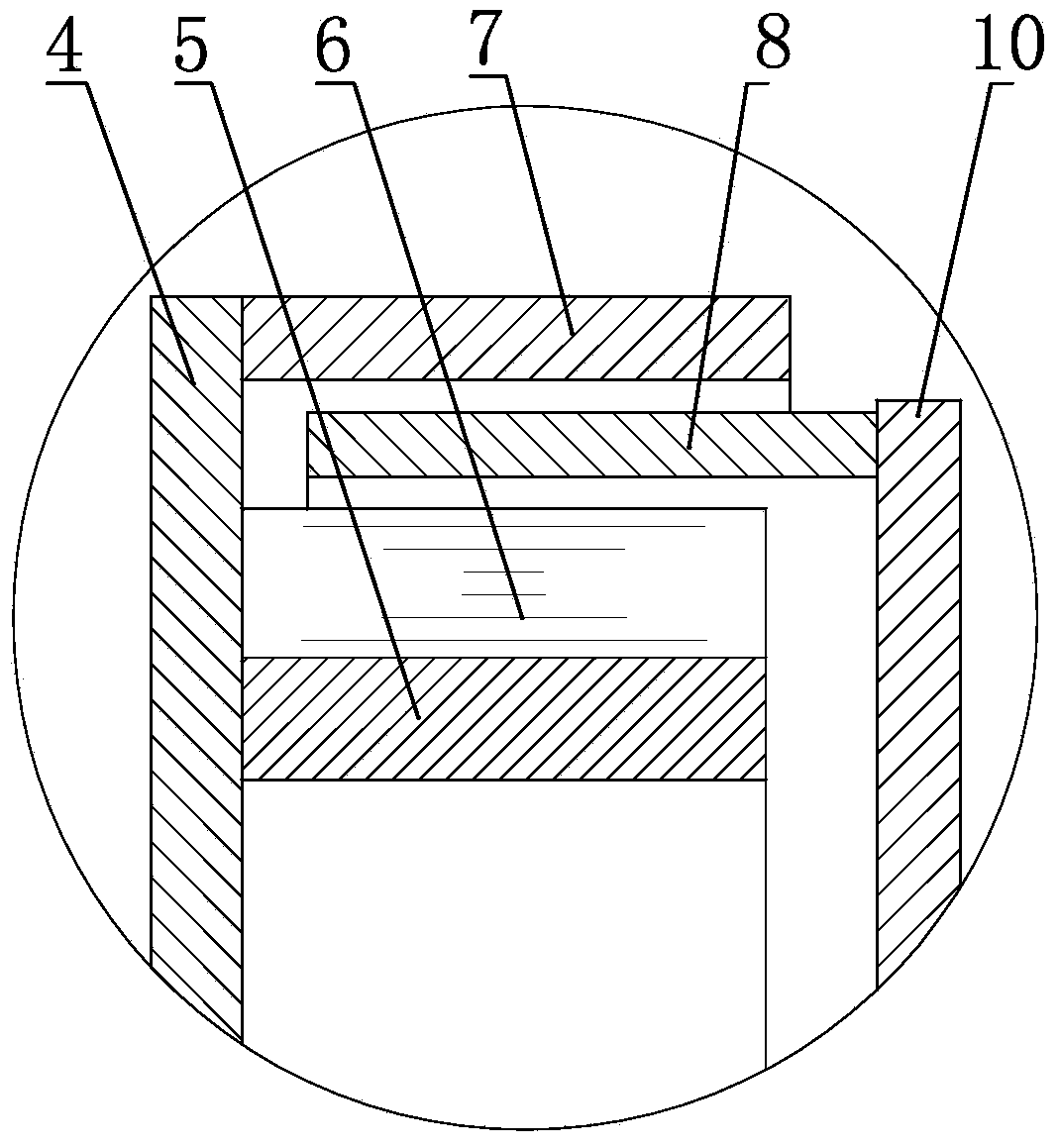
[0022] Such as figure 1 As shown, the cylindrical turntable permanent magnet coupler of the present invention includes a split and coaxial first shaft 1 and a second shaft 13, the first shaft 1 is provided with a permanent magnet turntable 4, and the permanent magnet turntable 4 is provided with The inner layer cylinder 5, the outer layer cylinder 7 and the magnet-carrying body 6, the inner layer cylinder 5 and the outer layer cylinder 7 are arranged correspondingly inside and outside along the diameter direction of the rotating disk on the permanent magnet turntable 4, and the magnet-carrying body 6 is placed in the inner layer cylinder 5 and Between the outer layer cylinders 7, the inner layer cylinder 5, the outer layer cylinder 7 and the permanent magnet turntable 4 are all ferromagnetic materials, the carrier magnet 6 is a non-ferromagnetic material, and a circle of permanent magnets is installed on the carrier magnet 6, and the magnetic pole direction of the permanent mag...

Embodiment 2

[0035] see image 3 , The structure of the permanent magnetic coupler in this embodiment can also achieve the purpose of speed reduction and energy saving, and one conductor cylinder 8 can be provided, which is arranged between the outer layer cylinder 7 and the magnet carrier 6 .

Embodiment 3

[0037] see Figure 4 , The structure of the permanent magnetic coupler in this embodiment can also achieve the purpose of speed reduction and energy saving, and one conductor cylinder 8 can be provided, which is arranged between the inner cylinder 5 and the magnet carrier 6 .


PUM


Abstract

The invention discloses a cylindrical rotating plate permanent magnet coupler which comprises a first shaft and a second shaft. The first shaft and the second shaft are coaxial. The first shaft is provided with a permanent magnet rotating plate provided with an inner layer cylinder, an outer layer cylinder and a carrying magnet. The inner layer cylinder and the outer layer cylinder are arranged inside and outside the permanent magnet rotating plate in the diameter direction of the rotating plate in a corresponding mode. The carrying magnet is arranged between the inner layer cylinder and the outer layer cylinder and provided with a circle of permanent magnets. The polar direction of the permanent magnets is perpendicular to the axis of the permanent magnet rotating plate. Every two adjacent magnets are installed in a hetero-polar mode. The second shaft is provided with a conductor rotating plate provided with at least one conductor cylinder. The conductor cylinders are arranged in the gap between the inner layer cylinder and the carrying magnet and the gap between the outer layer cylinder and the carrying magnet. Transmission of different kinds of torque is achieved by adjusting the coupling area between rotors, the purposes of isolating vibration, reducing the speed and saving the energy are achieved, installing and debugging are easy, axial moving of a certain degree is allowed, torque transmission between the two parts can be achieved, and the purposes of isolating vibration, reducing the speed and saving the energy are achieved.

Description

technical field [0001] The invention relates to a driving device, in particular to a permanent magnet coupler of a cylindrical turntable adopting the principle of permanent magnet eddy current induction. Background technique [0002] The existing motor systems basically have the phenomenon of large horses and small carts, and the waste of electric energy is serious, and the traditional mechanical coupling inevitably transmits vibration from one end to the other through the coupling, which obviously does not have the ability to isolate vibration and Energy-saving performance, the "12th Five-Year Plan for Energy Conservation and Emission Reduction" clearly proposes to use energy-saving technologies such as permanent magnet eddy current flexible transmission to optimize system operation and control, and improve the overall operating efficiency of the system. [0003] In this case, the permanent magnet coupler is a new ideal choice in the field of motor energy saving. Contents...

Claims


Application Information

Patent Timeline
Patent Type & Authority Applications(China)
IPC IPC(8): H02K51/00
Inventor 王荣松
Owner QINGDAO SPRING ENERGY TECH
Why Eureka
Try Eureka