Electrically-induced light-emitting line with arrow direction indication function

An electroluminescent wire, arrow direction technology, applied in electroluminescent light source, electric light source, light source and other directions, can solve the problem of unable to produce direction indication effect, unable to realize light with direction indication arrow pattern, etc.

Inactive Publication Date: 2014-07-09
SHANGHAI DONGZHOU IND
View PDF9 Cites 10 Cited by
  • Summary
  • Abstract
  • Description
  • Claims
  • Application Information

AI Technical Summary

Problems solved by technology

Because people are evacuating in a hurry in an emergency dark situation, simple and clear direction pattern indication is the key to safe evacuation. T...

Method used


Image

  • Electrically-induced light-emitting line with arrow direction indication function
  • Electrically-induced light-emitting line with arrow direction indication function
  • Electrically-induced light-emitting line with arrow direction indication function

Examples


Embodiment Construction

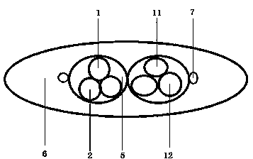
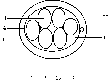
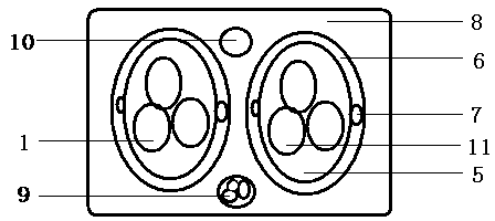
[0027] An electroluminescent wire with an arrow direction indication, which includes: two parallel multi-core luminescent wires, an external electrode 7, and a colored transparent plastic layer 6. The multi-core luminous wire is composed of more than one insulated metal wire. figure 1 The multi-core light-emitting structure diagram is composed of 1, 2, and 3, which are spirally wound or twisted according to the inclination angle, and the surface is coated with a light-emitting layer. The insulated metal wires in the two parallel multi-core luminescent wires are respectively combined according to the inclination angle to form a direction arrow, forming a "person" or "eight" shape, and the inclination angle is preferably equal to 45 degrees. And place the external electrode 7, the external electrode is closely connected with the light-emitting layer, and sealed with a colored transparent plastic layer. When a plurality of insulated metal wires and external electrodes are co...


PUM


Abstract

An electrically-induced light-emitting line with the arrow direction indication function comprises two parallel multi-core light-emitting lines, an external electrode and a colorful transparent plastic layer. The electrically-induced light-emitting line is characterized in that the multi-core light-emitting lines are composed of one or more insulation metal wires and are spirally twisted or stranded according to the inclination angle rule, and the surfaces of the multi-core light-emitting lines are coated with light-emitting layers; the insulation metal wires in the multi-core light-emitting lines are correspondingly combined according to the inclination angle to form direction arrows, the external electrode is placed, and the insulation metal wires are sealed through the colorful transparent plastic layer; when the insulation metal wires are correspondingly connected with a multi-path drive controller, the electrically-induced light-emitting line produces light-emitting arrow direction indication patterns. The electrically-induced light-emitting line can be applied to the fields such as electrical devices, wires, cables, advertisements, building safety, fire protection illumination and building decoration. The electrically-induced light-emitting line is simple in production technology and suitable for scale production.

Description

technical field [0001] The invention belongs to the technical field of electroluminescent wire application. Background technique [0002] The structure of the existing multi-core electroluminescent wire is mainly a combination of multiple luminescent core wires or multiple luminescent wires. Its basic structure is a metal electrode plus an insulating medium layer, a luminescent layer, a transparent conductive layer, and a winding outer electrode. A plurality of luminescent wires are wound, and the external electrode is connected with a voltage of 80-110V to produce spiral luminescence. This structure, material, and formula have been clearly described in Chinese patents 97121158.2, 03236894.1, 02274250.6, and 02228676.4. The flashing of the luminous line uses a winding structure of multiple metal core electrodes. By controlling the opening and closing of the circuit, a single flashing multi-wire combination is completed, and the overall control is cycled segment by segment to...

Claims


Application Information

Patent Timeline
IPC IPC(8): H05B33/12
Inventor 郑岩陈磊全丽华蒋贇余秋芳周金水陆红梅何帮缵
Owner SHANGHAI DONGZHOU IND
Why Eureka
Try Eureka