Chair

A technology for chairs and components, applied in chairs, reclining chairs, rocking chairs, etc., can solve the problems of increasing the travel of moving parts, unable to make detailed adjustments, etc., and achieve the effect of miniaturization

Inactive Publication Date: 2014-07-09
OKAMURA MFG CO LTD
View PDF11 Cites 0 Cited by
  • Summary
  • Abstract
  • Description
  • Claims
  • Application Information

AI Technical Summary

Problems solved by technology

[0012] (B) Only step-by-step adjustments can be made to apply force in the direction of raising the backrest, and fine adjustments cannot be made
[0013] (C) It is necessary to increase the stroke of the moving parts, so the layout of the force applying unit and other parts has to be changed, or the whole device becomes larger

Method used


Image

  • Chair
  • Chair
  • Chair

Examples


Embodiment Construction

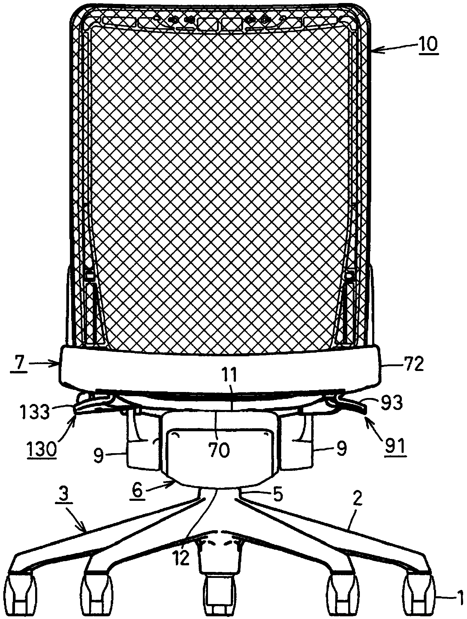
[0091] Hereinafter, one embodiment of the present invention will be described based on the drawings. In addition, in each figure, it refers to left and right when viewed from the front.

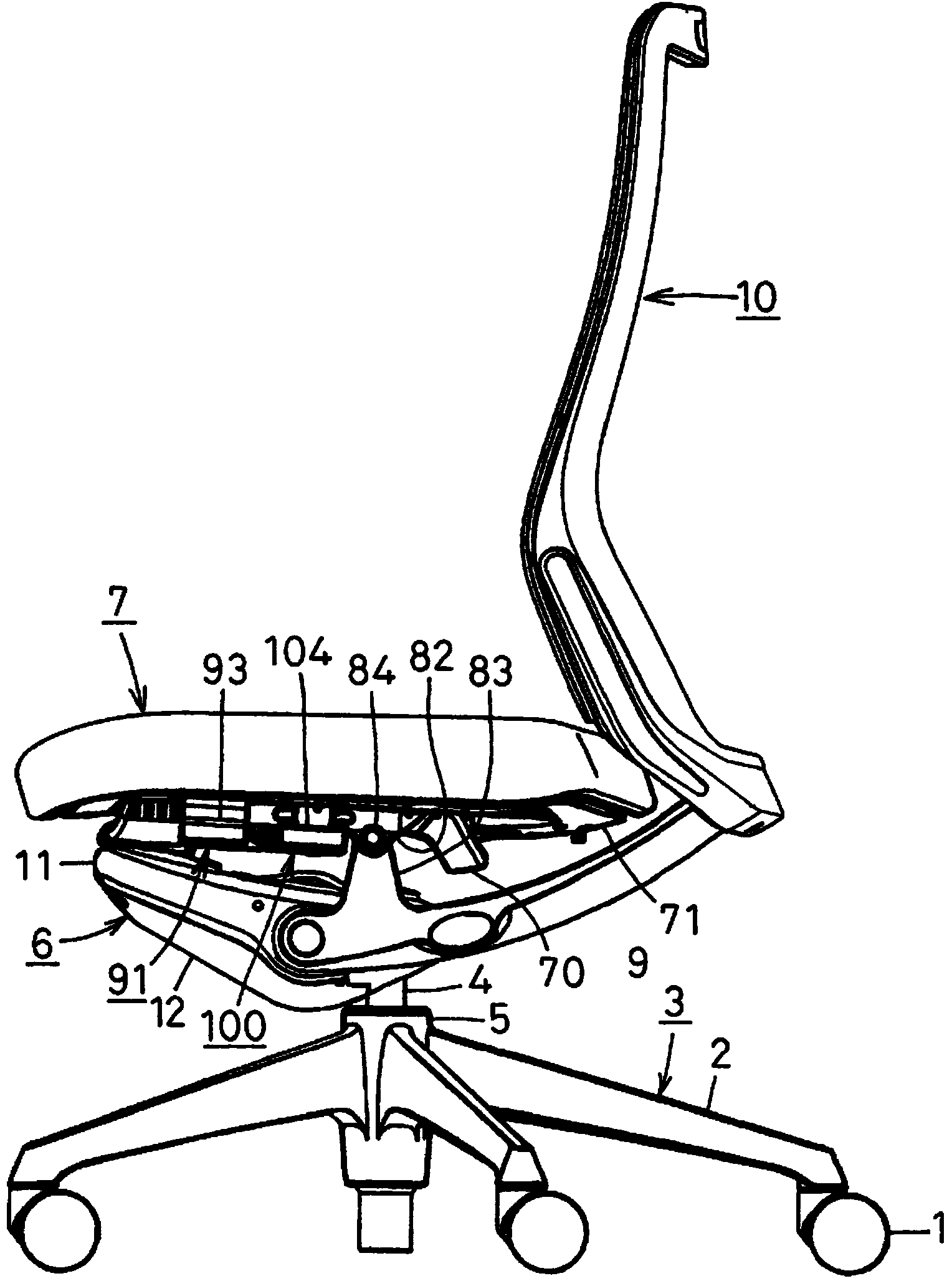
[0092] figure 1 is the front view of the chair of the present invention, figure 2 It is a side view of the chair of the present invention.

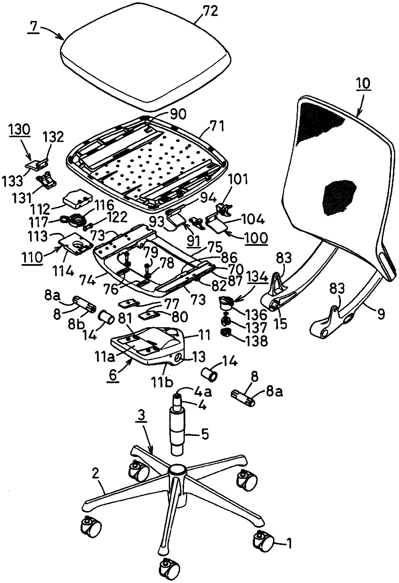
[0093] The chair is equipped with: a leg body 3 having five radial leg bars 2 equipped with casters 1 at the front end; (Gas Spring, see image 3 , Figure 14 etc.); the support 6 towards the upper front, its rear end is supported on the upper end of the foot column 4; the seat 7, which is supported above the support 6 as described later; the left and right pair of backrests towards the rear support Rods 9,9, their front ends are directed towards a left and right pair of pivots 8,8 (refer to image 3 , Figure 7 etc.) and are pivotally connected to the support 6; and the backrest 10, which is supported by the rear ends of the two backrest support...


PUM


Abstract

Provided is a chair in which a biasing force that acts on a back can be greatly changed even if the stroke of a moving member is small, thereby enabling the whole device to be compact, and in which the biasing force that acts on the back can be adjusted steplessly and with a light force. A biasing force transmission member (41) reverses the biasing force of a biasing means that acts on a tip portion of the biasing force transmission member (41) which is a point of effort (Q) with with a point abutting a fulcrum member (49) working as a fulcrum (P) for a lever, transmits the biasing force to a base end of the biasing force transmission member (41) which is a point of load (R) in order to bias the back in a direction in which the back will be upright, and moves the fulcrum member (49) along a side edge of the biasing force transmission member (41); on a pressure receiving side in order to be able to adjust the biasing force that acts on the back.

Description

technical field [0001] The present invention relates to a chair capable of reclining a backrest and adjusting the biasing force of a biasing unit that biases the backrest in a direction to raise the backrest. Background technique [0002] As a conventional adjustment unit for adjusting the biasing force of the biasing unit that biases the backrest in a direction to raise the backrest, there are the following configurations: [0003] (A) Rotate the nut screwed with the threaded part of the adjustment rod by the handle, thereby changing the position of the end of the winding start side of the coil spring biasing in the direction to raise the backrest, thereby changing the initial load of the coil spring structure (for example, refer to Patent Document 1). [0004] (B) A structure in which a plurality of rubber torsion springs are arranged along pivots that rotate integrally with the backrest, and biasing forces of the rubber torsion springs are selectively applied to the pivo...

Claims


Application Information

Patent Timeline
Patent Type & Authority Applications(China)
IPC IPC(8): A47C3/026A47C7/40
CPCA47C1/03255A47C1/03266A47C1/03272A47C1/024
Inventor 小田洋一郎
Owner OKAMURA MFG CO LTD
Why Eureka
Try Eureka