Belt driving roller including electroviscous force developing member, and belt driving device using same

Inactive Publication Date: 2016-03-03
RICOH KK
View PDF18 Cites 13 Cited by
  • Summary
  • Abstract
  • Description
  • Claims
  • Application Information

AI Technical Summary

Benefits of technology

[0015]an electroviscosity retaining member of which surface viscos

Problems solved by technology

However, correction by means of swaying of a driven roller as described in JP-A No. 2000-198568 will be ineffective due to wear of the surface of this roller due to continuous use.
Restriction of the belt skew by means of a guide member provided on the edge of the belt as described in JP-A No. 2000-147950 may cause the belt to be torn because a stress concentrates on a portion of the bel

Method used


Image

  • Belt driving roller including electroviscous force developing member, and belt driving device using same
  • Belt driving roller including electroviscous force developing member, and belt driving device using same
  • Belt driving roller including electroviscous force developing member, and belt driving device using same

Examples


example 1

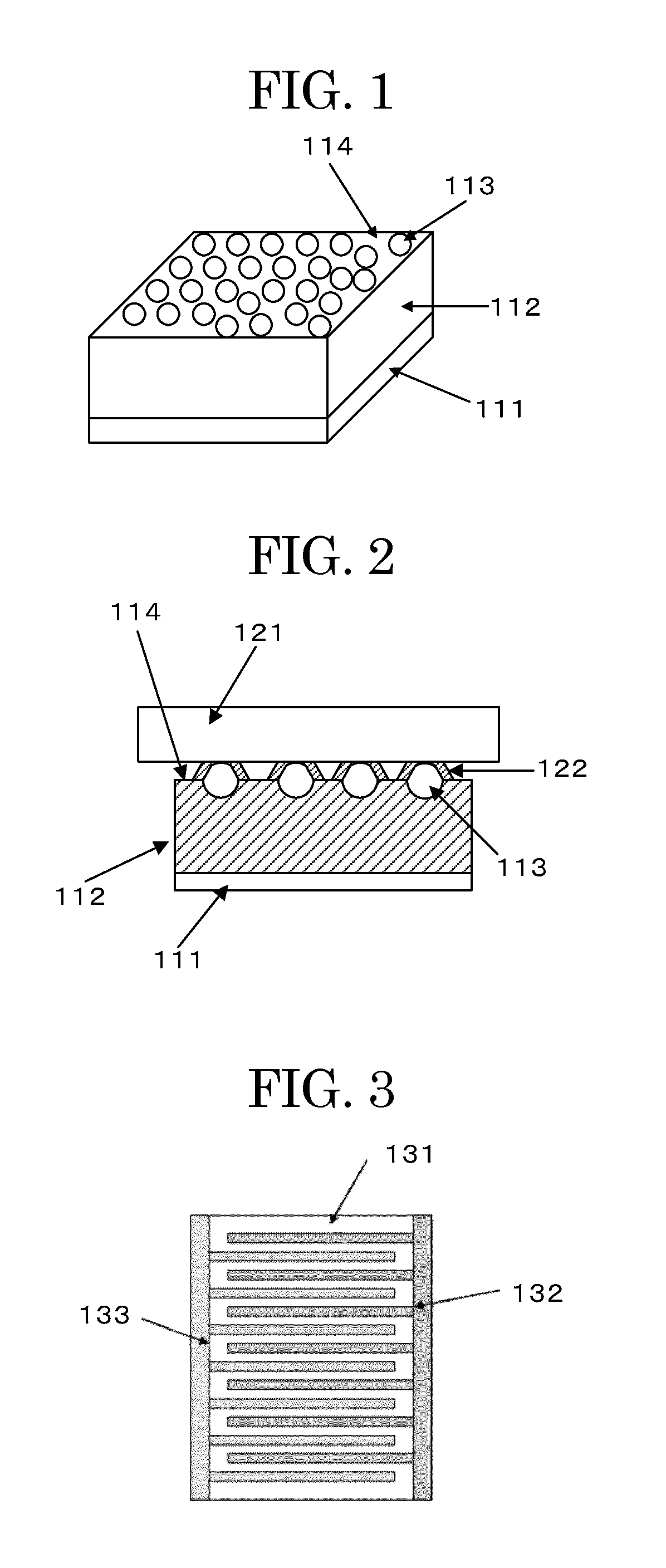
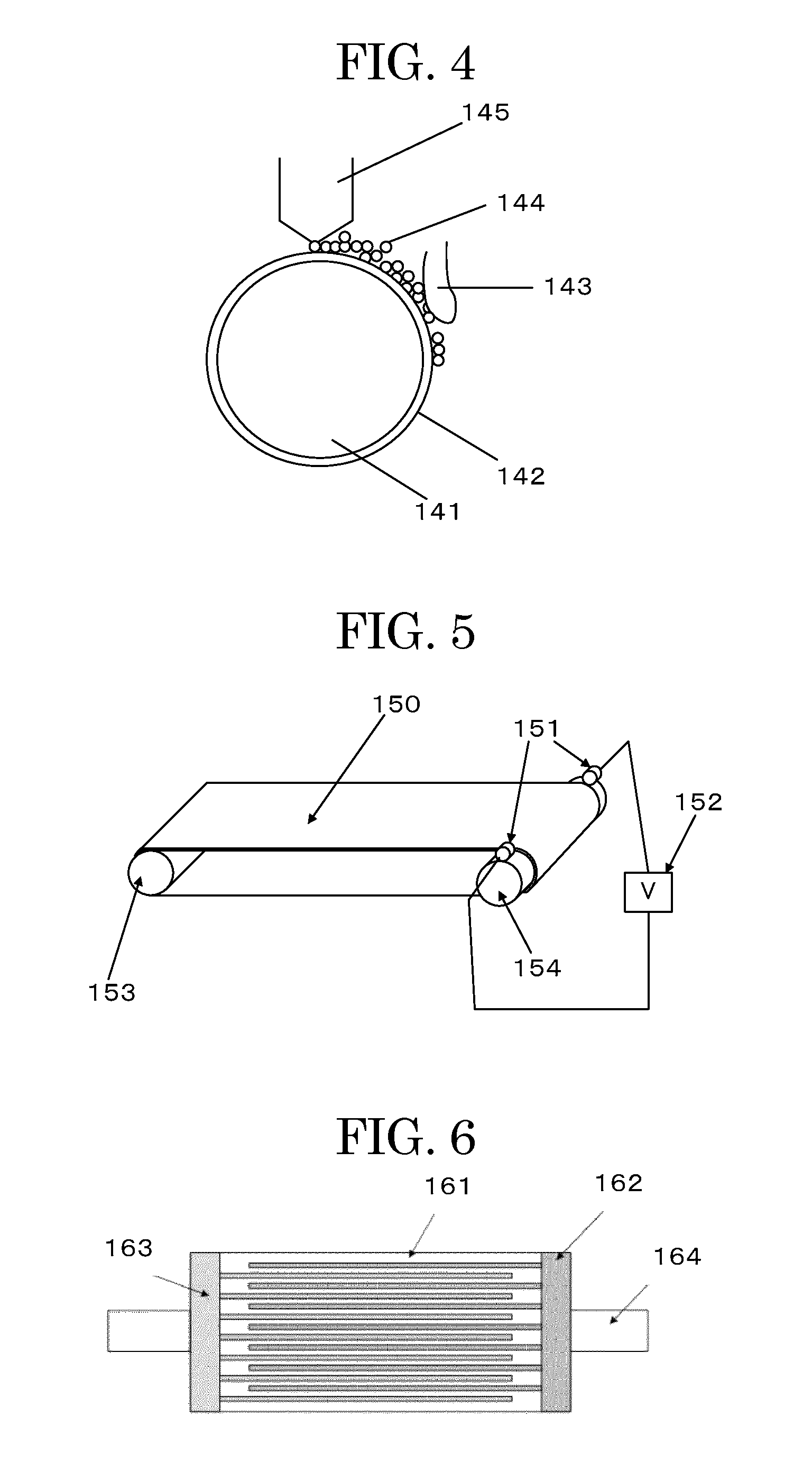
[0106]A polyimide film of which surface was plated with a copper foil was etched to thereby form a base member film over which a comb-teeth-shaped electrode composed of alternately arranged positive and negative electrodes as shown in FIG. 3 was formed. The obtained base member film was wound over the surface of a roller made of SUS and having an outer diameter of 40 mm and a width of 360 mm.

[0107]Next, the elastic layer was formed over the surface of the roller according to the following.

[0108]A method for forming the elastic layer will be described.

[0109]First, the materials shown below were blended and kneaded with a kneader, to thereby produce a rubber composition.

Material Composition of Elastic Layer

[0110]An acrylic rubber (NIPOL AR12 manufactured by Zeon Corporation): 100 parts by mass

[0111]A stearic acid (beaded stearic acid TSUBAKI manufactured by NOF Corporation): 1 part by mass

[0112]A cross-linking agent (DIAK. NO 1 (hexamethylenediamine carbamate) manufactured by Dupont D...


PUM


Abstract

Provided is a belt driving roller for a belt driving device configured to drive and rotate an endless belt with at least one driving roller of a plurality of rollers over which the belt is hung by its internal surface, wherein the belt driving roller includes an electroviscosity retaining member of which surface viscosity force reversibly changes under an effect of an electric field.

Description

BACKGROUND OF THE INVENTION[0001]1. Field of the Invention[0002]The present invention relates to a belt driving roller including an electroviscous force developing member, and a belt driving device using the same.[0003]2. Description of the Related Art[0004]Generally, belt driving devices for driving and rotating an endless belt are configured to rotate the belt by rotating driving rollers by means of a tensile force between the driving rollers and a frictional force that are caused because the belt is tensed by the plurality of rollers over which the belt is hung by its internal surface (back surface).[0005]According to this method, a belt skew, which is a shift of the belt toward an edge during its continuous rotation, occurs due to tensile force variations in the direction of the width of the belt. Hence, it is necessary to correct the belt skew by providing such a mechanism as described in Japanese Patent Application Laid-Open (JP-A) Nos. 2000-272772, 2000-198568, and 2000-14795...

Claims


Application Information

Patent Timeline
IPC IPC(8): F16H7/18G03G15/08
CPCG03G15/0806F16H7/18G03G15/2017G03G15/1615G03G2215/00156G03G2215/1623G03G2215/2032
Inventor AOTO, JUNYOSHINO, MASAKIKINO, TOMOKOAOYAMA, TOJIROSHIMIZU, YUTA
Owner RICOH KK
Why Eureka
Try Eureka