Non-friction clutch

A clutch and non-friction technology, applied in the field of clutches, can solve the problems of severe friction plate wear, short service life, and reduce operating costs, and achieve the effects of strong torque transmission, avoiding frequent maintenance, and reducing operating costs

Active Publication Date: 2014-07-16
CHONGQING LONGWANG ELECTROMECHANICAL
View PDF5 Cites 7 Cited by
  • Summary
  • Abstract
  • Description
  • Claims
  • Application Information

AI Technical Summary

Problems solved by technology

[0002] At present, the clutches used in vehicles mostly adopt the friction structure, and the clutch transmission is realized through the engagement and separation between the active friction plate and the driven friction plate. Generally, the clutch requires frequent operations during the driving process of the vehicle to achieve effective control of the vehicle. And with the gradual increase in the number of vehicles, the smoothness of road traffic is getting worse and worse, which increases the operating frequency of the clutch, resulting in serious wear and tear of the friction plate, frequent maintenance, and the replacement and installation of the friction plate is difficult, and the operating cost is relatively high. high, short service life
[0003] Therefore, in order to solve the above problems, a non-friction clutch is needed to avoid the problems of frequent maintenance and short life due to component wear, and reduce operating costs.

Method used


Image

  • Non-friction clutch
  • Non-friction clutch
  • Non-friction clutch

Examples


Embodiment Construction

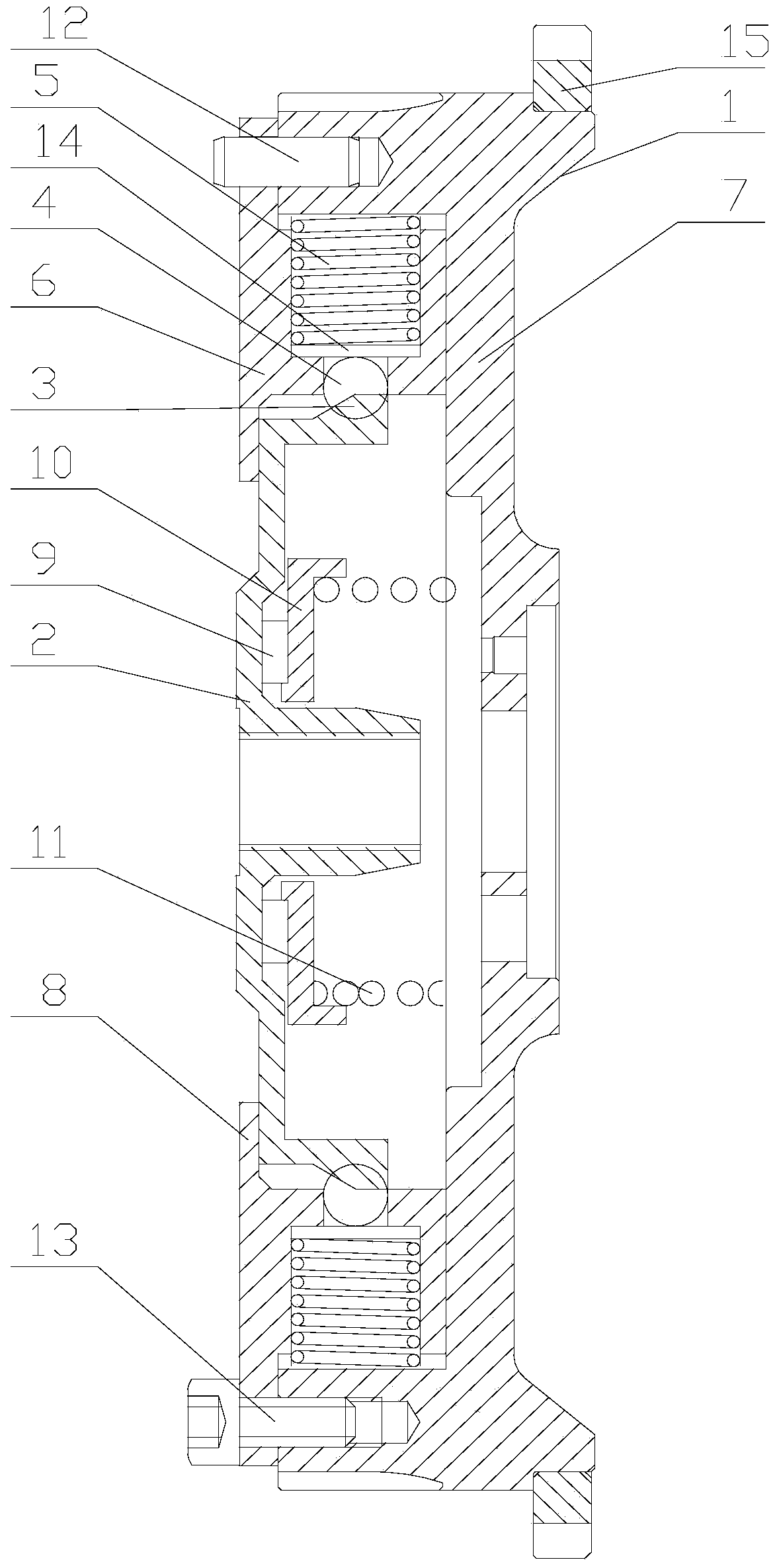
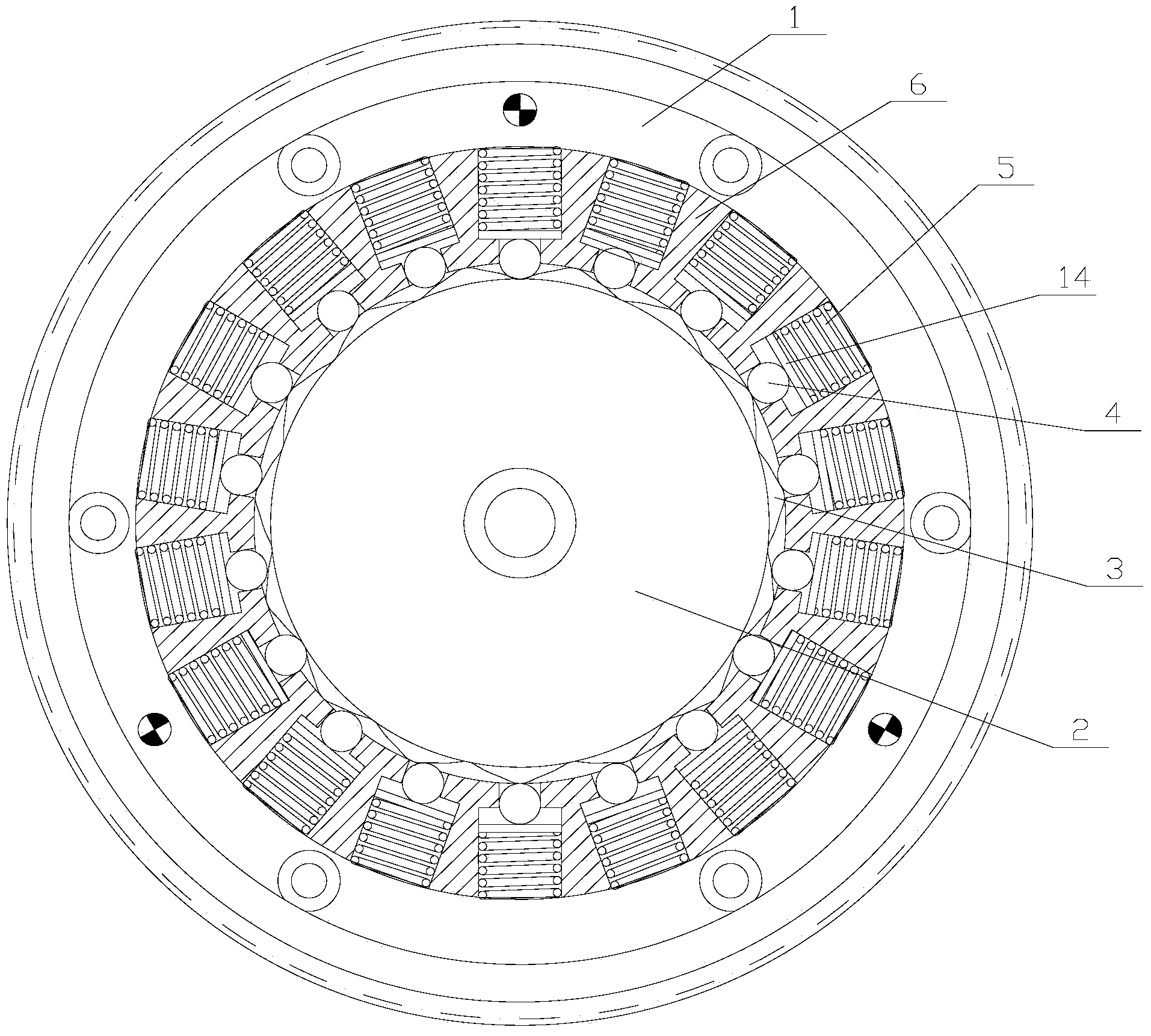
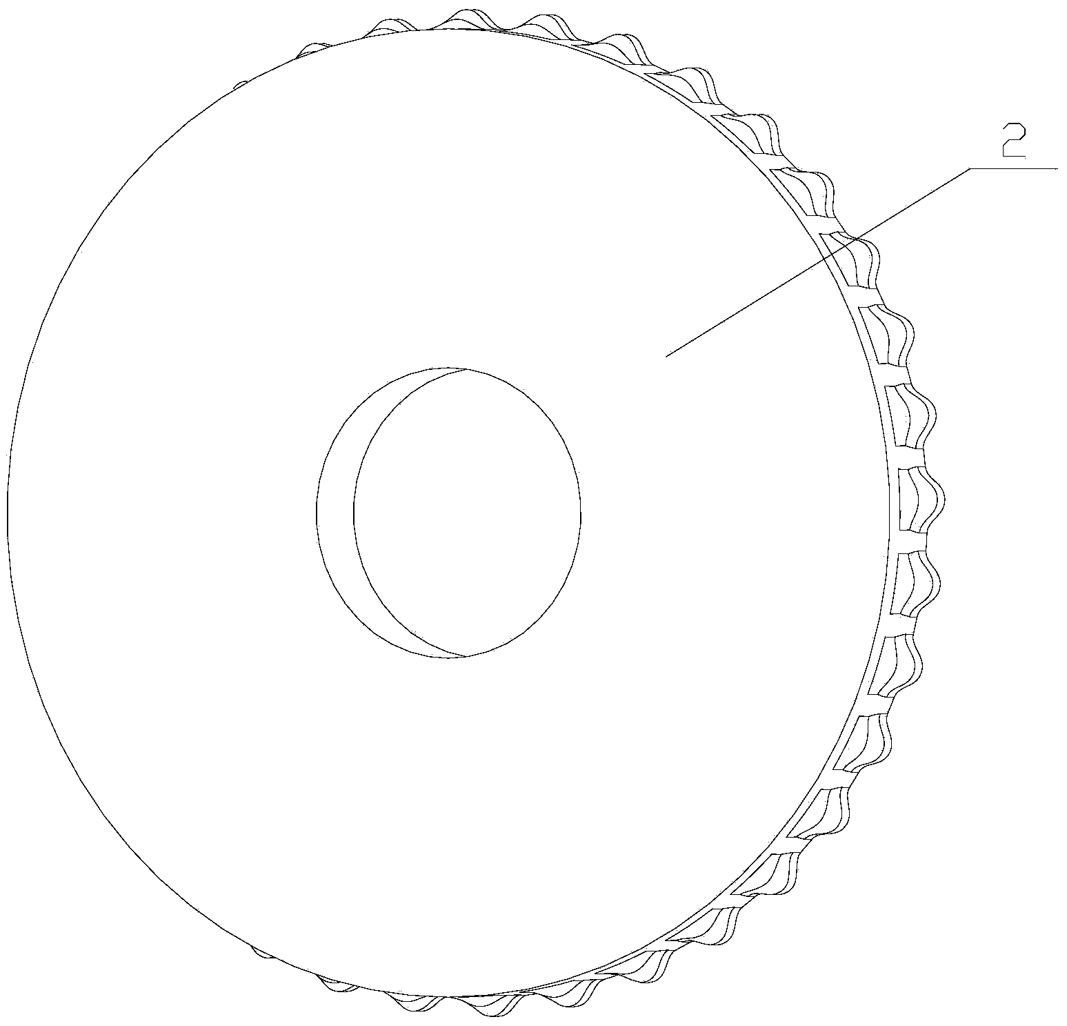
[0019] figure 1 It is a structural schematic diagram of the present invention; figure 2 for figure 1 left view of image 3 It is a three-dimensional view of the driven part, as shown in the figure: the non-friction clutch of this embodiment includes the driving part 1, the driven part 2 and the transmission part; the driving part 1 and the driven part 2 are coaxially fitted together And rotation fit, gear teeth 3 are provided on the rotation mating surface of the driven part 2; the transmission part includes a floating block radially floating on the rotation mating surface of the active part 1 and meshing with the gear teeth for transmission The tangential direction angle between the floating block and the point of action of the gear teeth 3 is continuously variable; the rotating mating surface of the driven part 2 refers to the mating surface on the driven part 2 that is rotationally matched with the active part 1; the rotation of the active part 1 The mating surface refe...


PUM


Abstract

The invention discloses a non-friction clutch which comprises a driving part, a driven part and a transmission part. The driving part and the driven part are coaxially assembled together in a sleeved mode and matched with each other in a rotary mode, and the rotary matching face of the driven part is provided with gear teeth; the transmission part comprises a floating block which is radially arranged on the rotary matching face of the driving part in a floating mode and is in mesh transmission with the gear teeth; the tangential angle of the floating block and the action point of the gear teeth can be changed continuously; the transmission part is of a transmission structure where the floating block is matched with the gear teeth, and the tangential angle of the action point of the floating block and the gear teeth is made to be changed continuously with in a certain range to generate continuous variable joint force; when the tangential angle is relatively large, equal-torque output is achieved, torque transmission capacity is strong, dynamic performance is good, meanwhile, the floating block and the gear teeth are in non-friction match so that the problems that overhaul is frequent and service life is short due to abrasion of the parts can be avoided, and operation cost is lowered.

Description

technical field [0001] The invention relates to a clutch, in particular to a non-friction clutch. Background technique [0002] At present, the clutches used in vehicles mostly adopt the friction structure, and the clutch transmission is realized through the engagement and separation between the active friction plate and the driven friction plate. Generally, the clutch requires frequent operations during the driving process of the vehicle to achieve effective control of the vehicle. And with the gradual increase in the number of vehicles, the smoothness of road traffic is getting worse and worse, which increases the operating frequency of the clutch, resulting in serious wear and tear of the friction plate, frequent maintenance, and the replacement and installation of the friction plate is difficult, and the operating cost is relatively high. High and short service life. [0003] Therefore, in order to solve the above problems, a non-friction clutch is needed to avoid the p...

Claims


Application Information

Patent Timeline
Patent Type & Authority Applications(China)
IPC IPC(8): F16D15/00
Inventor 郭军敬王吉龙
Owner CHONGQING LONGWANG ELECTROMECHANICAL
Why Eureka
Try Eureka