Method for inverting adiabatic temperature rise of concrete
An adiabatic temperature rise and concrete technology, applied in the field of obtaining the adiabatic temperature rise of concrete, can solve the problems of low test accuracy, unable to reflect concrete heat release process well, unable to completely prevent concrete heat dissipation, etc., and achieve a simple and clear formula. Effect
- Summary
- Abstract
- Description
- Claims
- Application Information
AI Technical Summary
Problems solved by technology
Method used
Image
Examples
Embodiment approach
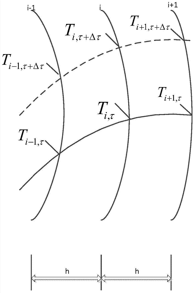
[0025] The invention measures the temperature of concrete at different measuring points at different times by arranging temperature sensors at different positions on the same section of concrete along the radial direction, and then calculates the temperature field through a differential method, and uses the minimum sum of the squares of the measured temperature and the calculated temperature difference to optimize the adiabatic inversion temperature rise. The specific method can be implemented as follows:
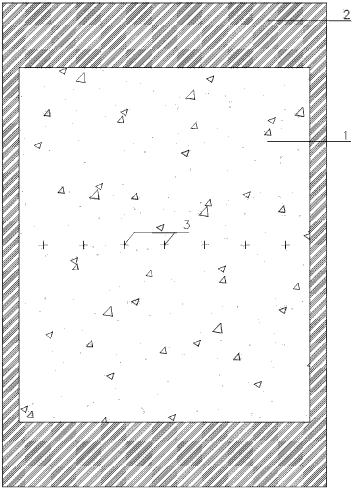
[0026] 1) Firstly, make a cylindrical hollow mold. The two sides are detachable for easy transportation and demoulding. Holes are left on both sides at the middle height. A layer of thermal insulation material [2] is laid on the lower part of the hollow mold to simulate radial one-dimensional heat dissipation. At the same time, thermal insulation materials are laid around the mold respectively, with a thickness of one-third to one-fifth of the lower thermal insulation mater...
Embodiment
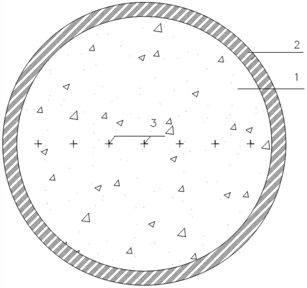
[0053] In a specific implementation, the inner diameter of the cylinder is 400mm and the height is 600mm. The insulation material adopts rubber and plastic sponge, 80mm of insulation material is laid on the upper and lower parts, and 20mm of insulation material is laid on the four sides. A total of seven temperature sensors are arranged on the middle height section, one of which is arranged in the center of the circle along the radial direction, and the sensor spacing is 50mm, as figure 2 shown. Read the temperature every 5 minutes, take the time step Δτ as 5min, and the thickness h of each layer as 50mm.
[0054] Divide the seven measurement positions into two groups, each group of measurement points are in the same radial direction, respectively figure 2 Sensor point 1234 and sensor point 7654 are shown. The initial measurement of each group is taken as the initial condition, the measurement of the first group of No. 1 and No. 4 sensors is the boundary condition, and th...
PUM
 Abstract
Description
Claims
Application Information
 - R&D
- Intellectual Property
- Life Sciences
- Materials
- Tech Scout
- Unparalleled Data Quality
- Higher Quality Content
- 60% Fewer Hallucinations
Browse by: Latest US Patents, China's latest patents, Technical Efficacy Thesaurus, Application Domain, Technology Topic, Popular Technical Reports.
© 2025 PatSnap. All rights reserved.Legal|Privacy policy|Modern Slavery Act Transparency Statement|Sitemap|About US| Contact US: help@patsnap.com


