

Fault diagnosis system
A fault diagnosis system and fault diagnosis technology, applied in the general control system, control/adjustment system, test/monitoring control system, etc., can solve problems such as inconvenient vehicle maintenance and errors in diagnosis results, and improve accuracy and accuracy Effect
- Summary
- Abstract
- Description
- Claims
- Application Information
AI Technical Summary
Problems solved by technology
Method used
Image

Examples
Embodiment 1
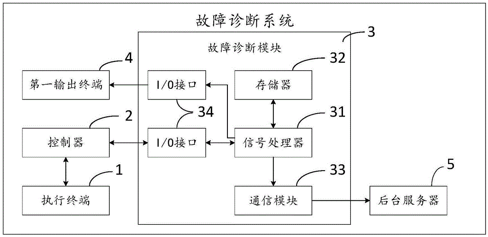
[0040] As the fault diagnosis system described above, the difference of this embodiment is that, as figure 2 As shown in the structural diagram of Embodiment 1 of the fault diagnosis system of the present invention, the fault diagnosis module 3 includes: a signal processor 31, a memory 32, a communication module 33 and a plurality of I / O interfaces 34; the signal processor 31 passes through the I / O interface 34 Connect with the controller 2 and the first output terminal 4 respectively, receive the first monitoring signal, the second monitoring signal and the operation signal, compare it with the data in the memory 32 for diagnosis, and pass the normal signal through The I / O interface 34 is transmitted to the first output terminal 4, and the abnormal signal is transmitted to the first output terminal 4 and the communication module 33; the memory 32 receives and stores the first monitoring signal, the second monitoring signal, the The running signal and its diagnosis result are u...
Embodiment 2
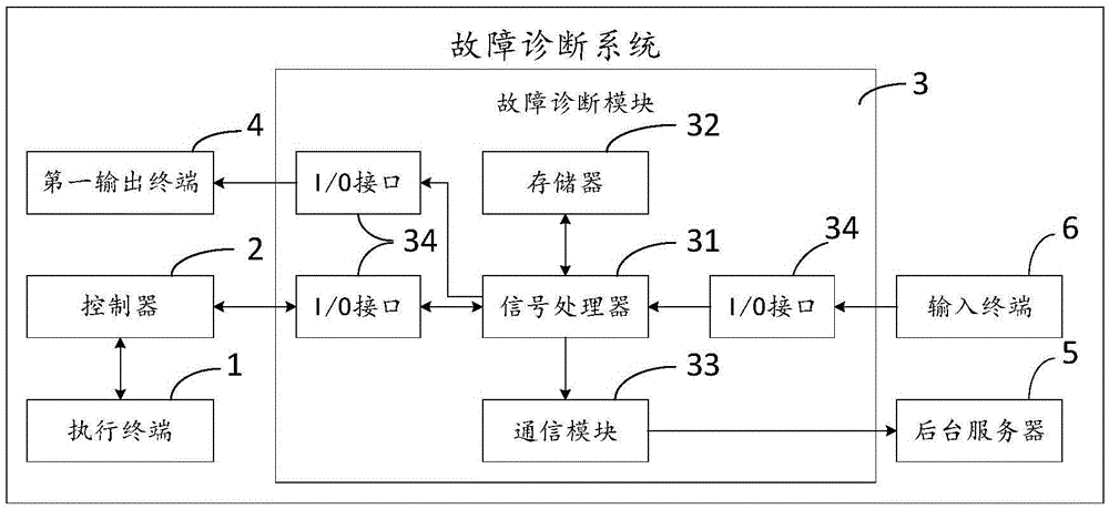
[0044] As the fault diagnosis system described above, the difference of this embodiment is that, as image 3 As shown in the structural diagram of Embodiment 2 of the fault diagnosis system of the present invention, the fault diagnosis system further includes an input terminal 6 connected to a signal processor 31 through an I / O interface 34 .
[0045] The input terminal 6 can be an input device (such as an input keyboard, a terminal that can input content such as an iPad) to input control commands to the signal processor 31, and control the signal processor 31 to perform specific actions, such as updating data in the memory 32, or updating the A diagnostic method for receiving the first monitoring signal, the second monitoring signal and the running signal; it may also be an external running signal collecting device, so that in the case of a controller failure, the signal of the internal components of the vehicle is input to signal processing device 31; it can also be used as ...
Embodiment 3
[0047] As the fault diagnosis system described above, the difference of this embodiment is that, as Figure 4 As shown in the structure schematic diagram of the fault diagnosis system communication module of the present invention, described communication module 33 comprises: WiFi module 331, GPS module 332, USB module 333 and GPRS module 334; Establish contact, transmit described abnormal signal; GPS module 332 establishes contact with background server 5 by remote control, transmit described abnormal signal; USB module 333 establishes contact with background server 5 by the mode of data line, transmits described abnormal Signal; the GPRS module 334 transmits the abnormal signal to the background server 5 via the communication network.
[0048] In this way, the way for the communication module 33 to establish contact with the background server 5 is added, so that the fault diagnosis module 3 in the fault diagnosis system can establish contact with the background server 5 under...
PUM
 Abstract
Description
Claims
Application Information