Method for laying submarine pipeline leakage detection optical cable

A submarine pipeline and leakage detection technology, which is applied in the direction of optical fiber/cable installation, etc., can solve the problems of inability to realize the protection of the entire line of the optical cable along the pipeline, increased laying costs, and complex structures.

Active Publication Date: 2014-07-16
E TECH ENERGY TECH DEV CORP
View PDF6 Cites 16 Cited by
  • Summary
  • Abstract
  • Description
  • Claims
  • Application Information

AI Technical Summary

Problems solved by technology

[0006] 2. The structure of fixing the optical cable on the pipe is slightly complicated, which leads to an increase in laying costs, and the structure needs to be further simplified
[0007] 3. The full line protection of the optical cable along the pipe cannot be realized. Only the intermittent part of the optical cable is installed in the optical cable fixing device. In this way, when the pipeline bound with the sensing optical cable is buried below the seabed mud surface through the operation of the trenching machine or the optical cable When put into normal use, it is impossible to completely avoid damage to the optical cable

Method used


Image

  • Method for laying submarine pipeline leakage detection optical cable
  • Method for laying submarine pipeline leakage detection optical cable
  • Method for laying submarine pipeline leakage detection optical cable

Examples


Embodiment Construction

[0030] In order to further understand the invention content, characteristics and effects of the present invention, the following examples are given, and detailed descriptions are as follows in conjunction with the accompanying drawings:

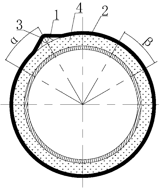
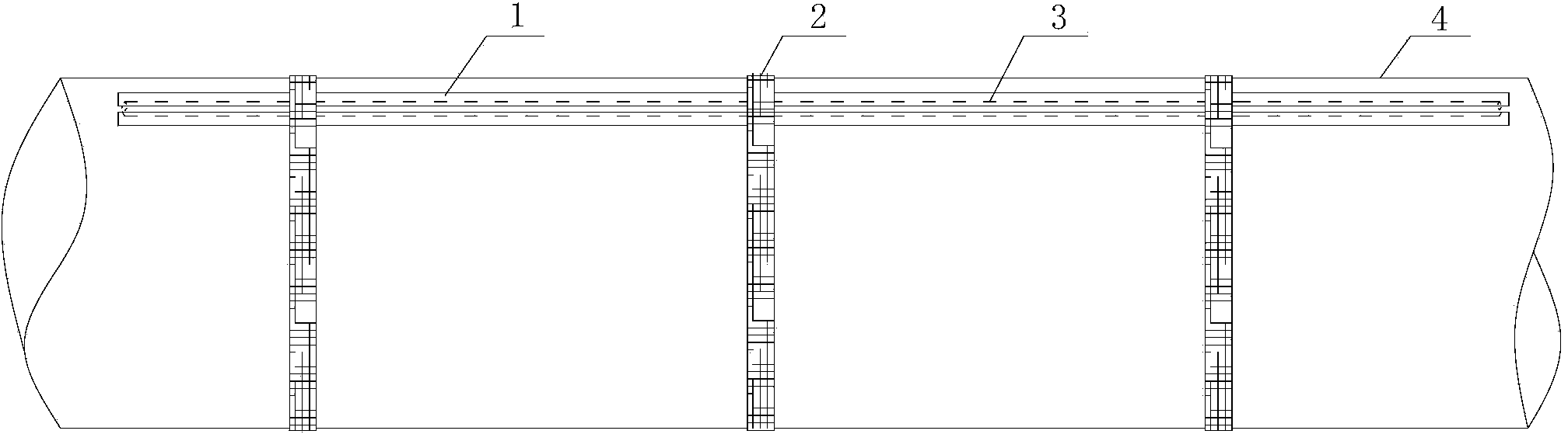
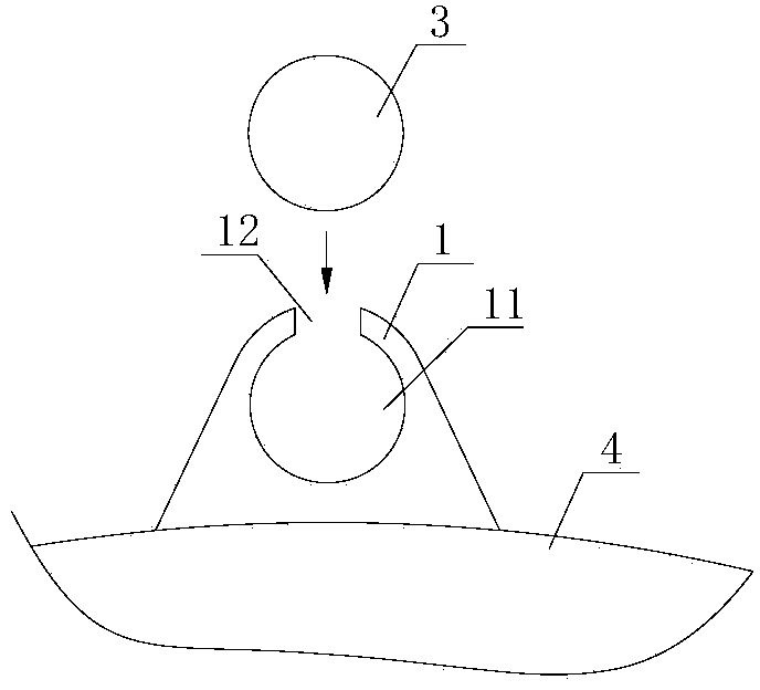
[0031] see Figure 1-3 , a method for laying a submarine pipeline leak detection optical cable, comprising the following laying steps:

[0032] 1) Arrange the pay-off rack wound with the sensor optical cable at the stern of the pipe-laying ship, and place the materials for laying on the construction site on the pipe-laying ship. Pads 1, glue and a plurality of flexible straps 2. Specifically, the optical cable installation groove is arranged longitudinally along the rubber pad, and the flexible binding strip is made of non-metallic material weaving.

[0033] 2) Along the longitudinal direction of the pipeline, use glue to glue the rubber pads on the outer surface of the pipeline in the way of head-to-tail connection. Specifically, when one ...


PUM


Abstract

A method for laying a submarine pipeline leakage detection optical cable includes the steps that a pay-off rack is arranged on the stern of a pipe laying ship, and rubber pad strips, glue and flexible binding belts are arranged in the construction position; the rubber pad strips adhere to the outer surface of a pipeline through glue in a subsequent end-to-end connecting mode; the pay-off rack is controlled to release the sensing optical cable and the sensing optical cable is installed in an optical cable mounting groove of the rubber pad strips; one flexible binding belt is bound to the outer envelope surface formed by the pipeline and the rubber pad strips every certain distance; the pipeline is laid on the seabed sequentially in a downstream mode; the pipeline is buried under the submarine mud face through operation of a trencher; the completeness of the sensing optical cable is tested, and one end, connected with a platform or the land, of the sensing optical cable is connected into a system host through a terminal box. According to the method for laying the submarine pipeline leakage detection optical cable, laying of the optical cable is completed on the pipe laying ship, the operability is high, personnel investment is substantially saved, laying construction difficulty and laying cost are reduced, and laying efficiency is improved. The sensing optical cable is installed in the rubber pad strips which are longitudinally connected in a butted mode in sequence along the pipeline, and thus the whole optical cable can be protected.

Description

technical field [0001] The invention belongs to the field of safety monitoring of submarine oil and gas pipelines, in particular to a method for laying optical cables for leak detection of submarine pipelines. Background technique [0002] With the rapid development of my country's offshore oil exploitation, the number and length of offshore pipelines have increased dramatically. As the main transportation and storage equipment, submarine pipelines play an important role in the exploitation of offshore oil and gas resources, and have the characteristics of high investment, high risk and high return. However, its unique geographical location and complex environmental loads (corrosion, waves, ocean currents, earthquakes, and third-party damage, etc.) lead to frequent pipeline leakage accidents and are difficult to detect early. Once a pipeline leak occurs, it will cause serious economic losses ( Oil and gas fields shut down or reduce production, waste of resources) and enviro...

Claims


Application Information

Patent Timeline
Patent Type & Authority Applications(China)
IPC IPC(8): G02B6/50
Inventor 胡欣王宁张淑贞李再春赵志娟杨磊刘伟纪铁樑
Owner E TECH ENERGY TECH DEV CORP
Why Eureka
Try Eureka