Liquid crystal display panel

A technology of liquid crystal display panels and liquid crystal display devices, which can be applied to static indicators, instruments, nonlinear optics, etc., and can solve problems such as difficult implementation

Inactive Publication Date: 2014-07-16
LENOVO (BEIJING) CO LTD
View PDF4 Cites 6 Cited by
  • Summary
  • Abstract
  • Description
  • Claims
  • Application Information

AI Technical Summary

Problems solved by technology

However, these two technologies need to improve the driving circuit of the liqu

Method used


Image

  • Liquid crystal display panel
  • Liquid crystal display panel
  • Liquid crystal display panel

Examples


Embodiment Construction

[0018] The technical solutions in the embodiments of the present invention will be clearly and completely described below with reference to the accompanying drawings in the embodiments of the present invention. Obviously, the described embodiments are only a part of the embodiments of the present invention, but not all of the embodiments. Based on the embodiments of the present invention, all other embodiments obtained by those of ordinary skill in the art without creative efforts shall fall within the protection scope of the present invention.

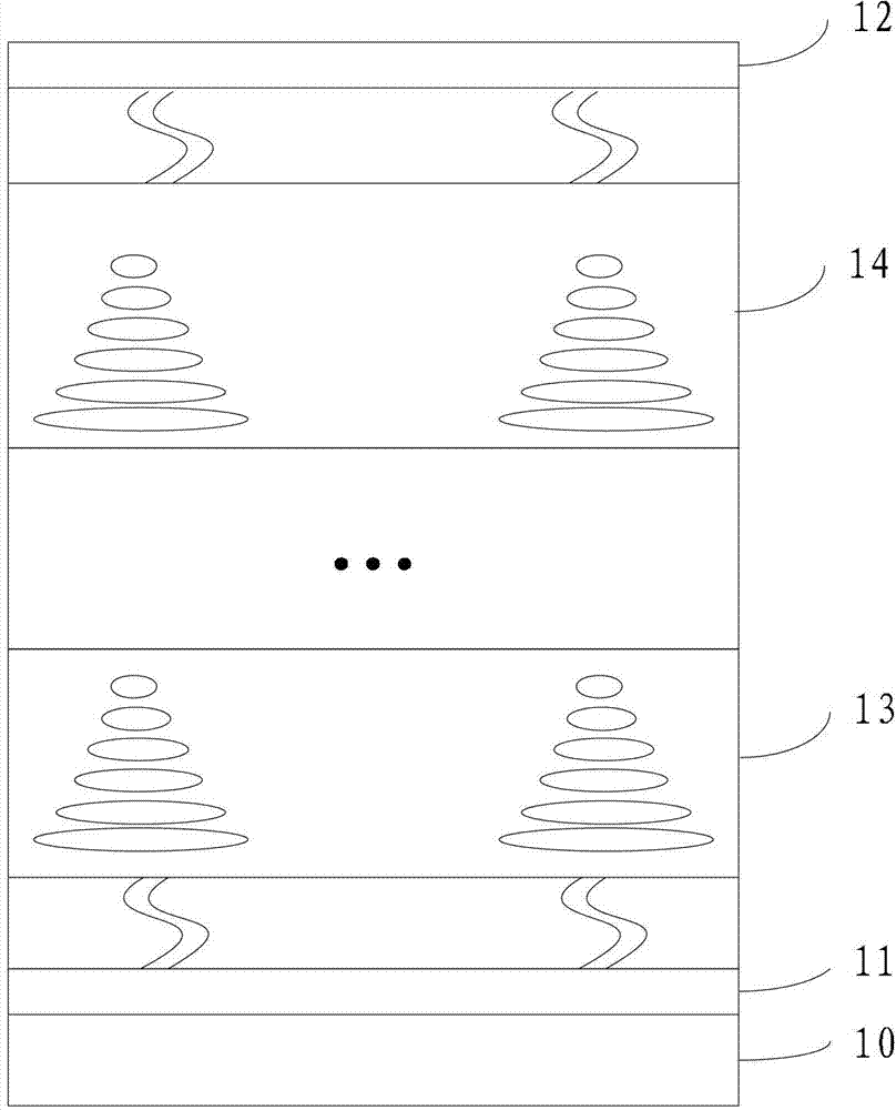
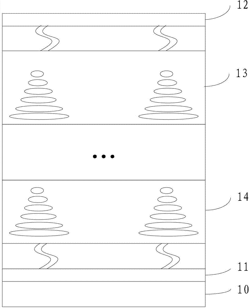
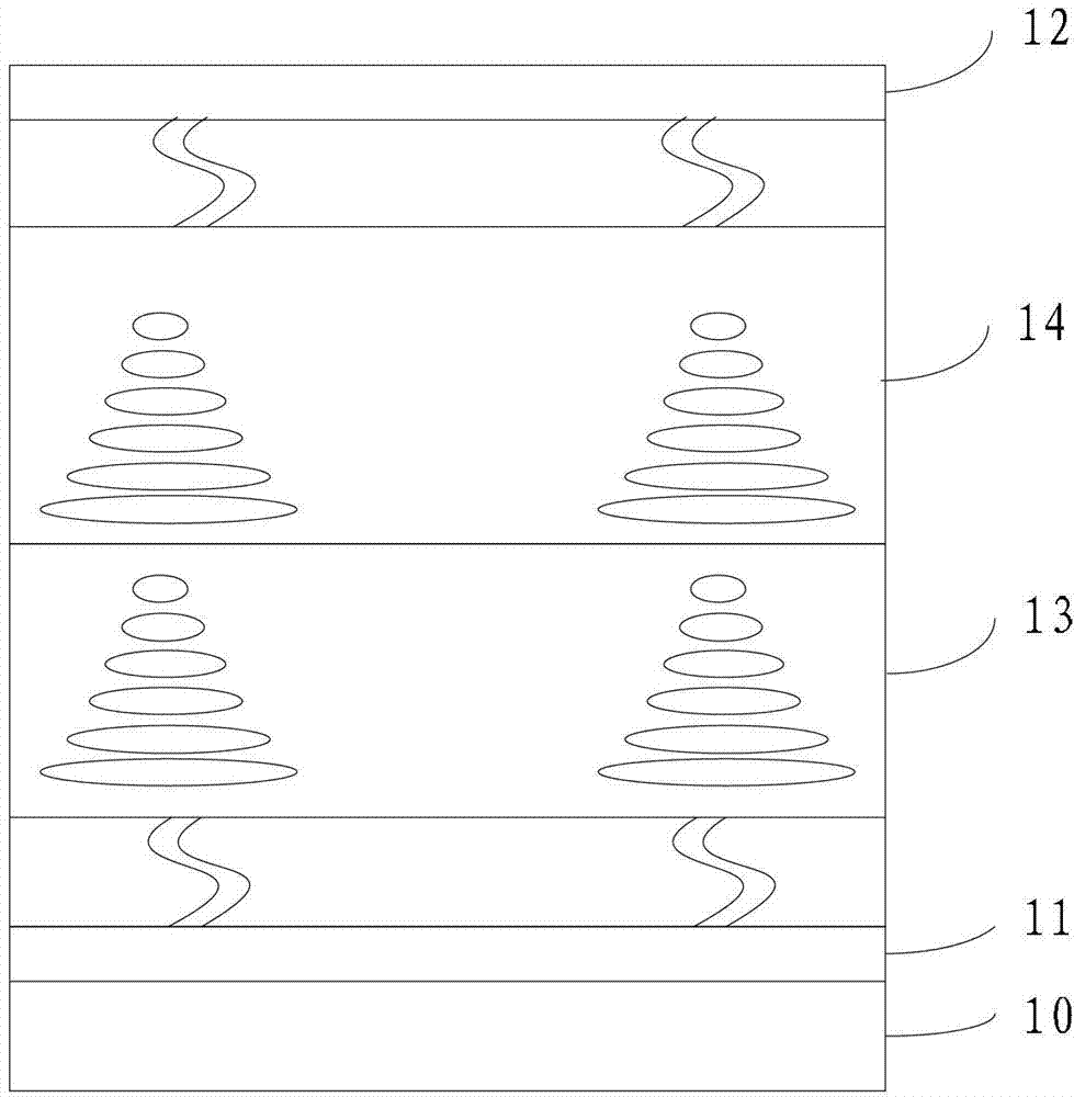
[0019] An embodiment of the present invention provides a liquid crystal display panel, such as figure 1 As shown, the liquid crystal display panel includes: a backlight module 10, a lower polarizer 11, an upper polarizer 12, a first liquid crystal layer 13 located between the lower polarizer and the upper polarizer, and a first liquid crystal layer 13 located between the lower polarizer and the upper polarizer At least one second liqu...


PUM


Abstract

An embodiment of the invention discloses a liquid crystal display panel. Gray level can be increased, and the display quality of the liquid crystal display panel is improved. The liquid crystal display panel comprises a backlight module, a lower polarizer, an upper polarizer, a first liquid crystal layer, at least one second liquid crystal layer and at least one driving circuit, wherein the first liquid crystal layer is positioned between the lower polarizer and the upper polarizer, the second liquid crystal layers are positioned between the lower polarizer and the upper polarizer, and the driving circuits are used for driving the second liquid crystal layers. The liquid crystal display panel is applicable to liquid crystal display technology.

Description

technical field [0001] The present invention relates to liquid crystal display technology, in particular to a liquid crystal display panel. Background technique [0002] With the development of science and technology, liquid crystal display technology has been widely used. Generally, the driving signal is divided into signals of different steps, and different energies are generated by the signals of different steps to drive the liquid crystal molecules, so that the pixels show the effect of gray scale. The gray scale represents the different brightness levels of a pixel from the darkest to the brightest. The more levels, the more delicate the picture effect that can be presented. [0003] To make the presented picture effect more delicate, the driving signal must be divided into more steps, and more precise energy is generated to drive the liquid crystal molecules, so that the liquid crystal molecules show more gray scales. [0004] To generate more gray scales, the drivin...

Claims


Application Information

Patent Timeline
IPC IPC(8): G02F1/133G02F1/1335G09G3/36
Inventor 张振华尚可
Owner LENOVO (BEIJING) CO LTD
Why Eureka
Try Eureka