Method and device for controlling control operation
A single-hand operation, touch point technology, applied in the input/output process of data processing, instruments, electrical and digital data processing, etc., can solve problems such as the inability to solve the blind spot of the thumb in single-hand operation, and improve user experience and flexibility. The effect of sex, simple and convenient operation
- Summary
- Abstract
- Description
- Claims
- Application Information
AI Technical Summary
Problems solved by technology
Method used
Image

Examples
Embodiment approach
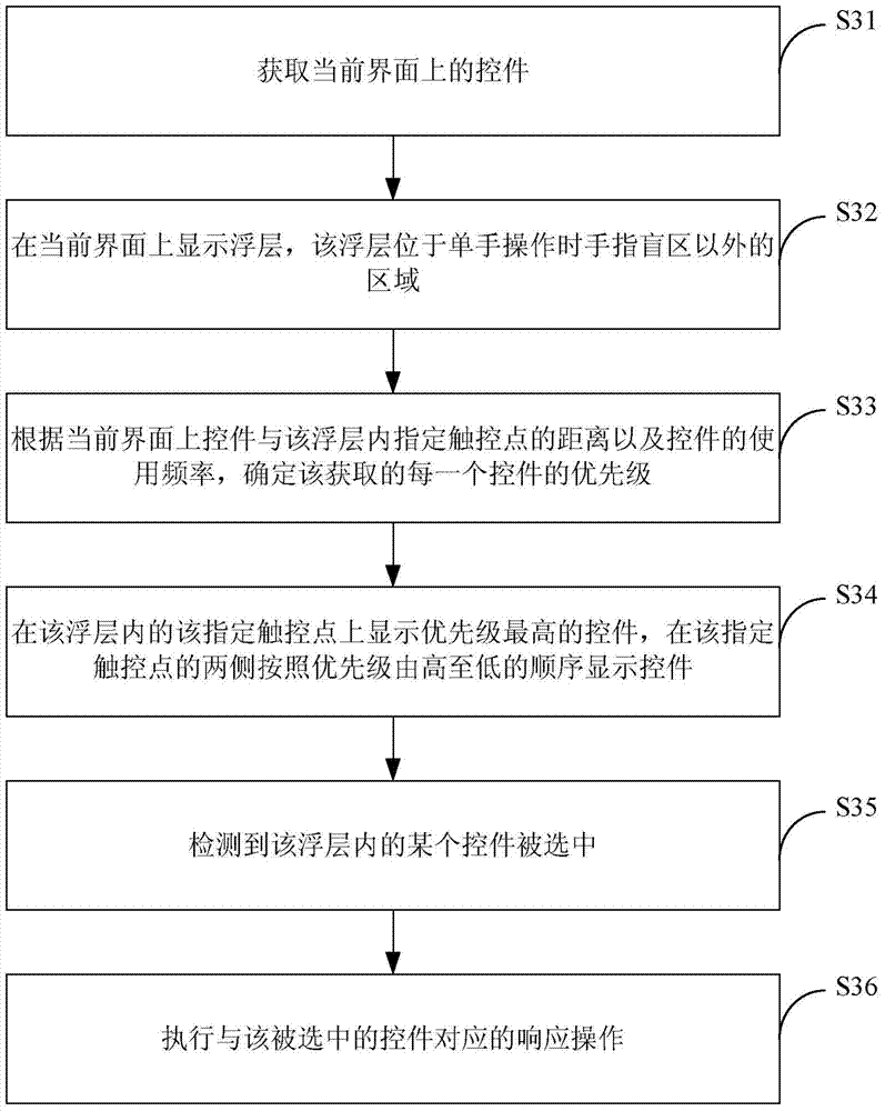
[0104] Wherein, the specified touch point in the floating layer may be any point in the floating layer, such as the center point of the floating layer. In one implementation manner, when the terminal is operated with one hand, the best touch point of the finger on the terminal screen may be set as the specified touch point. The optimal touch point may be the most comfortable and natural touch point with the user's finger on the terminal screen.
[0105] The designated touch point in the floating layer is usually a contact range, and the contact range includes a plurality of pixels, and the size and shape of the contact range are not specifically limited in this embodiment.
[0106] Among them, the priority of each acquired control can be determined according to the following formula:
[0107] P=D×K1+N×K2;
[0108] Among them, P is the priority of the control, D is the distance from the control on the current interface to the specified touch point in the floating layer, N is ...
PUM
 Abstract
Description
Claims
Application Information