Multi-pole double-throw travel switch

A travel switch, knife double throw technology, applied in the field of electronics, can solve the problems of conversion lag, complex structure, bulky conversion structure and drive structure, etc., and achieve the effect of compact structure, fast conversion and small volume

Active Publication Date: 2014-07-16
BEIJING RES INST OF MECHANICAL & ELECTRICAL TECH +1
View PDF4 Cites 8 Cited by
  • Summary
  • Abstract
  • Description
  • Claims
  • Application Information

AI Technical Summary

Problems solved by technology

[0003] At present, the existing direct-acting travel switches such as figure 1 As shown, limited by the structural form, there are only single-pole double-throw and double-pole double-throw forms. If they are combined with other forms to realize the multi-pole double-throw function, the conversion structure and drive structure are bulky, the conversion lags and the structure is complicated. Adapt to the current design requirements for miniaturization of electrical components

Method used


Image

  • Multi-pole double-throw travel switch
  • Multi-pole double-throw travel switch
  • Multi-pole double-throw travel switch

Examples


Embodiment Construction

[0019] The present invention will be described in detail below in conjunction with the accompanying drawings and specific examples.

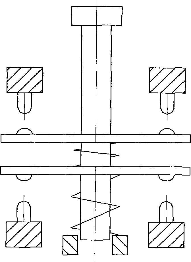
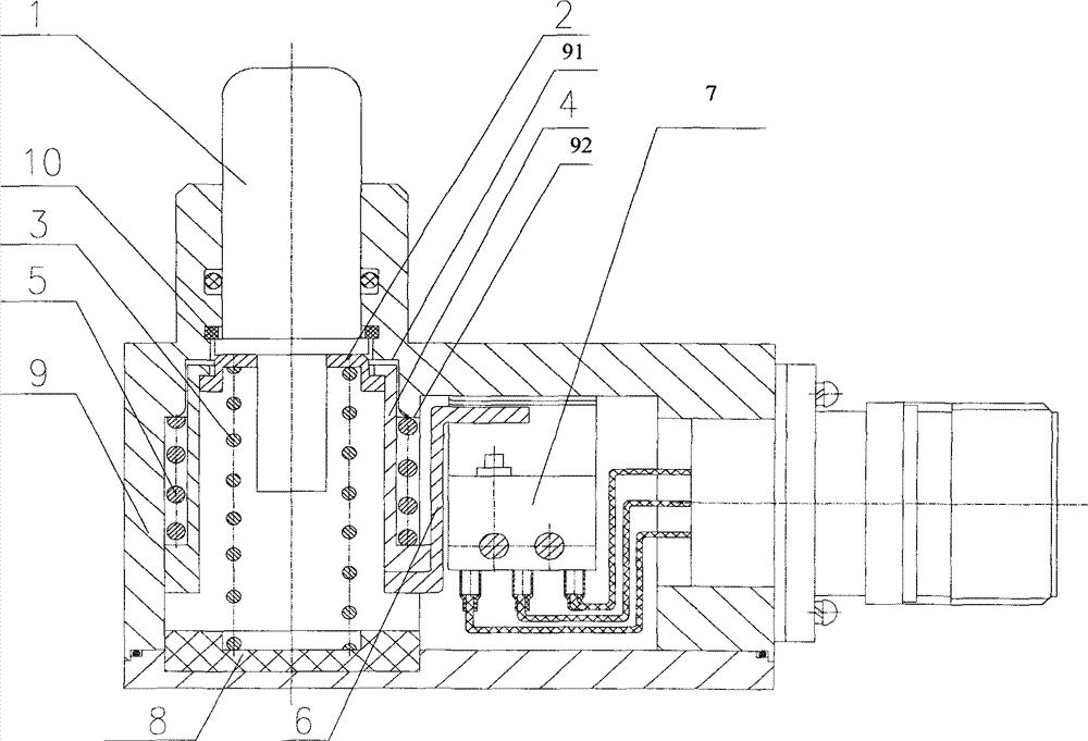
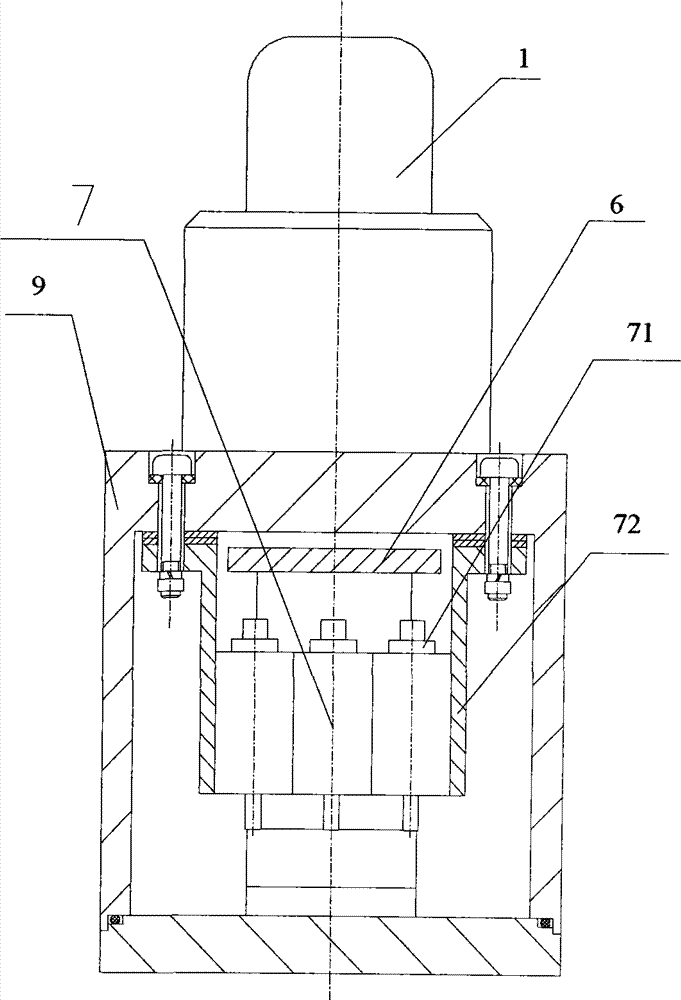
[0020] The present invention as figure 2 , 3 , Shown in 4, including driving mechanism, conversion mechanism 7 and output mechanism. The driving mechanism adopts the driving mode of double spring linkage and sliding sleeve hook combination, and the transmission operation of the switch conversion mechanism is realized through the movement of the push rod 1. drive mechanism such as figure 2 , 4 As shown, it includes a push rod 1, a compression spring sleeve 2, a main spring 3, a sliding sleeve 4, an auxiliary spring 5, a hook 6, a lower buffer pad 8, a housing 9 and an upper buffer pad 10, and the upper part of the inner cavity of the housing 9 is fixed on the upper The buffer pad 10 and the lower buffer pad 8 are fixedly installed at the bottom of the inner cavity of the housing 9 .

[0021] Housing 9 as figure 2 , 4 As shown, it is use...


PUM


Abstract

The invention provides a multi-pole double-throw travel switch comprising a driving mechanism, a switching mechanism and an output mechanism. The driving mechanism comprises a push rod, a compression spring sleeve, a main spring, a sliding sleeve, an auxiliary spring, a hook, a lower buffering cushion and a shell. The lower buffering cushion is fixedly installed at the bottom of an inner cavity of the shell, the sliding sleeve is installed in the inner cavity of the shell, the auxiliary spring is installed in a gap between the sliding sleeve and the shell, the sliding sleeve can slide in the vertical direction of the inner cavity of the shell under the elasticity action of the auxiliary spring, the push rod penetrates into the inner cavity of the shell from the upper portion of the shell, and the compression spring sleeve is placed below a boss in the middle of the push rod. The upper end of the main spring makes contact with the inner end face of the compression spring sleeve, the lower end of the main spring is fixed to the lower buffering cushion, the compression spring sleeve can slide in the vertical direction of the inner wall of the sliding sleeve under the elasticity action of the main spring, and one side of the sliding sleeve is fixedly connected with the bottom end of the hook. The mode of double spring linkage and sliding sleeve and hook combination is adopted for the driving mechanism, switch switching is finished through combining and positioning the structural parts, and the multi-pole double-throw travel switch has the advantages of being compact in structure, rapid in switching and small in size.

Description

technical field [0001] The invention relates to a multi-pole double-throw travel switch, which belongs to the field of electronic technology. Background technique [0002] The travel switch is a kind of electrical appliance that uses the movement of mechanical moving parts to trigger the circuit conversion device to realize the connection or disconnection of the circuit. The current travel switches are mainly divided into direct-acting, roller and micro-action according to the structure, and the electrical functions that can be realized are double-pole double-throw at most. With the improvement of circuit design integration in electrical systems, there is an urgent demand for multi-pole double-throw travel switches. [0003] At present, the existing direct-acting travel switches such as figure 1 As shown, limited by the structural form, there are only single-pole double-throw and double-pole double-throw forms. If they are combined with other forms to realize the multi-pol...

Claims


Application Information

Patent Timeline
Patent Type & Authority Applications(China)
IPC IPC(8): H01H3/16H01H5/12
Inventor 邹翔苗露刘明雒宝鹏徐峥峣曹勇岳玉洁胡尚锋张高峰
Owner BEIJING RES INST OF MECHANICAL & ELECTRICAL TECH
Why Eureka
Try Eureka