Bearing type universal chain

A chain and bearing technology, applied in the chain field, can solve the problems of narrow application range, huge transmission system, transmission of motion in the same plane, etc., to achieve the effect of load-bearing transportation

Active Publication Date: 2014-07-23
吴慧勇
View PDF5 Cites 8 Cited by
  • Summary
  • Abstract
  • Description
  • Claims
  • Application Information

AI Technical Summary

Problems solved by technology

The structure of the existing chain includes: a plurality of chain links, chain plates and a plurality of pin shafts are respectively provided on the two outer surfaces of adjacent chain links; the structure of the chain links is: fixed between two mutually parallel chain link plates Two chain rollers are spaced apart and arranged in parallel. The central through hole of the chain roller runs through the two chain link plates; the pin shaft hinges through the chain roller on the chain link, and its two ends are respectively fixed in the through holes of the chain plate , a plurality of chain plates are located on the outermost side of the chain, pin shafts are respectively fixed in the through holes at both ends of each chain plate, and the pin shafts are hinged in the chain rollers of the chain links, so that multiple chain plates and multiple pin shafts will Multiple links are hinged to form the existing chain. The existing chain has the following defects: the existing chain can only transmit motion in the same plane, and cannot complete synchronous linkage transmission in three-dimensional space. It needs to be realized by means of gears or other mechanisms, and there is a huge defect in the transmission system. At the same time, the existing chain can only transmit power, and cannot directly carry loads for transportation, so the scope of application is narrow

Method used


Image

  • Bearing type universal chain
  • Bearing type universal chain
  • Bearing type universal chain

Examples


Embodiment Construction

[0017] The present invention will be further described in detail below in conjunction with the accompanying drawings and specific embodiments.

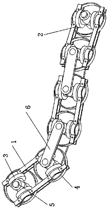
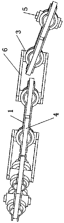
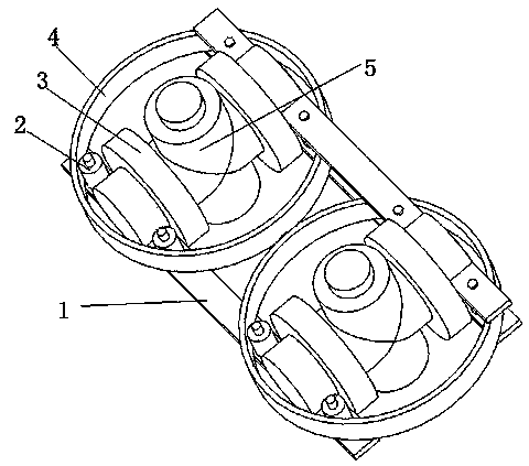
[0018] The invention discloses a bearing-type universal chain, the principle of which is to use the basic structure of the cross universal joint to realize the relative rotation of the cross shaft in the unit rail section in the vertical plane, and complete the vertical movement of two adjacent unit rail sections. Relative rotation in the plane, at the same time, two adjacent unit rail sections can rotate relatively in the horizontal plane, and finally solve the problem that the existing chain cannot be transmitted in multiple directions in three-dimensional space, and its specific structure includes at least two unit rail sections that can rotate relatively And the cross shaft connecting piece 6 used to connect the adjacent unit rail sections, the unit rail section includes two sets of running gear and the cross shaft frame 1 connecti...


PUM


Abstract

The invention discloses a bearing type universal chain. The bearing type universal chain comprises at least two unit rail links which can rotate relatively and cross shaft connecting pieces used for connecting the adjacent unit rail links. Each unit rail link comprises two walking devices and cross shaft frames which are connected with the two walking devices. The core component of each walking device is a cross shaft, wherein horizontal rotation and vertical rotation can be realized through a longitudinal shaft and a transverse shaft of each cross shaft. The bearing type universal chain has the advantages that each unit rail link is formed through the two cross shafts, the longitudinal shafts of the cross shafts, close to each other, of every two adjacent unit rail links are connected through the corresponding cross shaft connecting piece, rotation of the two adjacent unit rail links in the horizontal direction is realized, the transverse shafts of the two cross shafts of the same unit rail link are connected through the corresponding cross shaft frames, the two ends of each cross shaft frame and the two ends of the corresponding cross shafts are matched in a sleeved mode, relative rotation of the two cross shafts of the same unit rail link in the vertical direction is realized, and power transmission of the chain in three-dimensional space is realized in cooperation with a rail or a tension device at a turning position or a direction-changing position.

Description

technical field [0001] The invention relates to the technical field of chains capable of carrying loads and transmitting power. Background technique [0002] In the prior art, the chain that cooperates with the sprocket is a component that transmits the rotational motion of one side in the same plane to the other side to realize power transmission. The structure of the existing chain includes: a plurality of chain links, chain plates and a plurality of pin shafts are respectively provided on the two outer surfaces of adjacent chain links; the structure of the chain links is: fixed between two mutually parallel chain link plates Two chain rollers are spaced apart and arranged in parallel. The central through hole of the chain roller runs through the two chain link plates; the pin shaft hinges through the chain roller on the chain link, and its two ends are respectively fixed in the through holes of the chain plate , a plurality of chain plates are located on the outermost si...

Claims


Application Information

Patent Timeline
Patent Type & Authority Applications(China)
IPC IPC(8): F16G13/00F16G15/00B65G17/38
Inventor 吴慧勇
Owner 吴慧勇
Why Eureka
Try Eureka