Method for adjusting projection light angle of LED lamp

A technology of LED lamp and projected light, which is applied in the direction of light source, refractor, light source fixation, etc., can solve the problems of high cost and low assembly efficiency, and achieve the effect of low cost of use, easy light output angle, and adjustment of light output angle

Inactive Publication Date: 2014-07-23
DONGGUAN ARTS ELECTRONICS +1
View PDF8 Cites 11 Cited by
  • Summary
  • Abstract
  • Description
  • Claims
  • Application Information

AI Technical Summary

Problems solved by technology

[0003] The problem to be solved by the present invention is the defects of high cost and low assembly efficiency of the existing LED lamp assembly method. It provides an efficient LED lamp assembly method, which improves the assembly efficiency by connecting the various parts together by buckling them together. Efficiency, reduced production and use costs

Method used


Image

  • Method for adjusting projection light angle of LED lamp
  • Method for adjusting projection light angle of LED lamp
  • Method for adjusting projection light angle of LED lamp

Examples


Embodiment

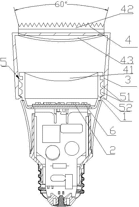
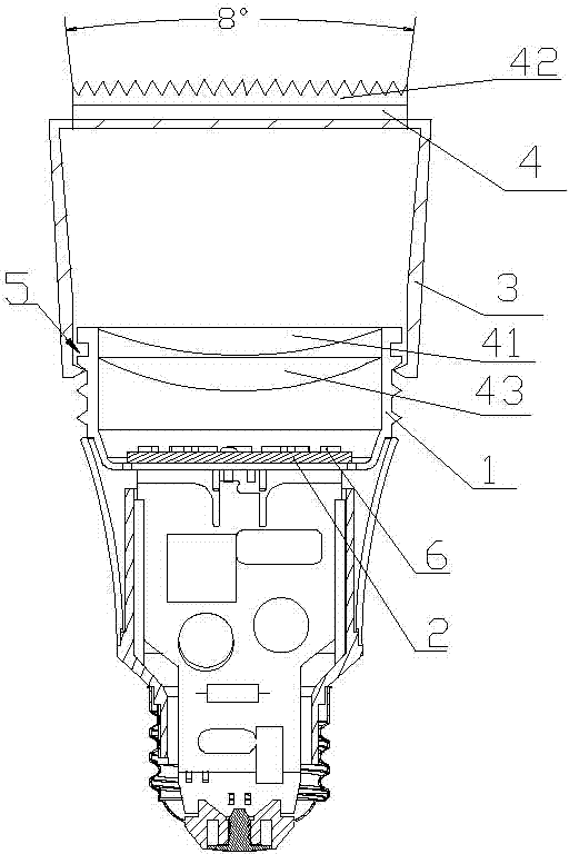
[0035] The method for adjusting the projected light angle of the LED lamp according to the present invention comprises the following steps:

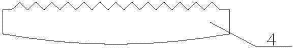
[0036] A lens group 4 is fixed in the light output direction of the LED lamp to achieve the effect of improving the brightness of the light output and lay the foundation for focusing. The lens group 4 can be set in the lamp cup 1 or lampshade 3 or in the lamp cup 1 and lampshade 3 respectively. lens. Then a focusing mechanism 5 is set between the lamp cup 1 and the lampshade 3 of the LED lamp, and the two are connected together through the focusing mechanism 5; lights6.

[0037] The manufactured LED lamp includes a lamp cup 1 with an LED lamp board 2 inside, and the lamp cup 1 is connected with a lampshade 3 through a focusing mechanism 5 . A lens group 4 is provided inside the end of the lampshade 3 for projecting the light emitted by the LED lamp on the LED lamp board 2 . The relative position of the lampshade 3 and the lamp cup 1 i...


PUM


Abstract

The invention relates to the technical field of LEDs, and particularly discloses a method for adjusting the projection light angle of an LED lamp. The method includes the following steps that a lens set is arranged in the light outlet direction of the LED lamp; a focusing mechanism is arranged between a lamp cup and a lampshade of the LED lamp, and the lamp cup and the lampshade are connected together through the focusing mechanism; the relative positions of the lampshade and the lamp cup is adjusted by the focusing mechanism to reach the projection angle corresponding to needed light brightness, and then light is emitted through the lens set. The focusing mechanism can be machined in a clamping groove mode or a chute mode or a spiral clamping groove mode. Collecting lenses and a Fresnel lens can be integrally formed or in adhering junction or stacked together. The method has the advantages that light brightness is high, the light outlet angle can be easily adjusted, and use cost is low.

Description

technical field [0001] The invention relates to the technical field of LEDs, in particular to a method for adjusting the projected light angle of an LED lamp. Background technique [0002] LED lamps are commonly used components in daily life. To realize the normal operation of LED lamps, lamp holders, power drive boards and LED lamp boards are required. After connecting these components, LED lamps can work. In existing LED lamps, the P pole and the N pole on the power drive board are respectively welded to the lamp cap, and the power drive board and the LED lamp board are also electrically connected by welding. On the one hand, such an installation method consumes a large amount of manpower to weld it, the labor cost is high, the installation time is long, and the assembly efficiency is low, thereby increasing the cost of the product. On the other hand, once one of the components breaks down, the components of the entire lamp will be scrapped, which increases the cost of us...

Claims


Application Information

Patent Timeline
Patent Type & Authority Applications(China)
IPC IPC(8): F21V14/06F21V5/04F21Y101/02
Inventor 陈政鸿施清德
Owner DONGGUAN ARTS ELECTRONICS
Why Eureka
Try Eureka